Dismantable protective window

a window and window frame technology, applied in the direction of window/door frame, warlike protection, frame fastening, etc., can solve the problems of unstable window system, no longer suitable for use, dangerous to inhabitants or visitors within the structure, etc., to prevent injury and damage, and facilitate mounting and dismounting

Inactive Publication Date: 2006-05-09
ARPAL ALUMINUM
View PDF17 Cites 39 Cited by
  • Summary
  • Abstract
  • Description
  • Claims
  • Application Information

AI Technical Summary

Benefits of technology

[0008]The present invention calls for a reinforced window system which may be fitted and mounted within an opening in a wall which may already be fitted with a window, e.g. a preservation window, without causing any damage hereto. It is an important feature of the invention that the reinforced window system be adapted for easy mounting and dismounting and that it be capable of absorbing blast energy, to prevent injury and damage from people and equipment within a space in which the window is fitted, even where it is mounted on a weak wall.
[0009]According to the present invention there is provided a reinforced window system for mounting within an opening in a wall, the window system comprising a frame fixable to the opening; said frame comprising an outside support panel and one or more fixable fixing members distributed on an inside of the frame; a reinforced window pane fixedly supported with a removable frame; said removable frame comprising a plurality of support members articulated to the support frame and adapted for engagement by the corresponding fixing members; and locking members for thereby positioning and fixing the removable frame within the frame.

Problems solved by technology

Such buildings are often fitted with their original window systems which at times are extremely old and in many cases are no longer suitable for use.
Even more so, such window systems may be unstable and loosely fitted within the opening in the wall in a manner which may be dangerous to inhabitants or visitors within the structure.
Still another problem concerned in particular with old buildings, but restricted thereto, is the weakness of the walls, which may at times be vulnerable themselves.
However, for most such reinforced systems it is required to remove the original window system which, as mentioned hereinabove, does not suit the present case.

Method used


Image

  • Dismantable protective window
  • Dismantable protective window
  • Dismantable protective window

Examples


Embodiment Construction

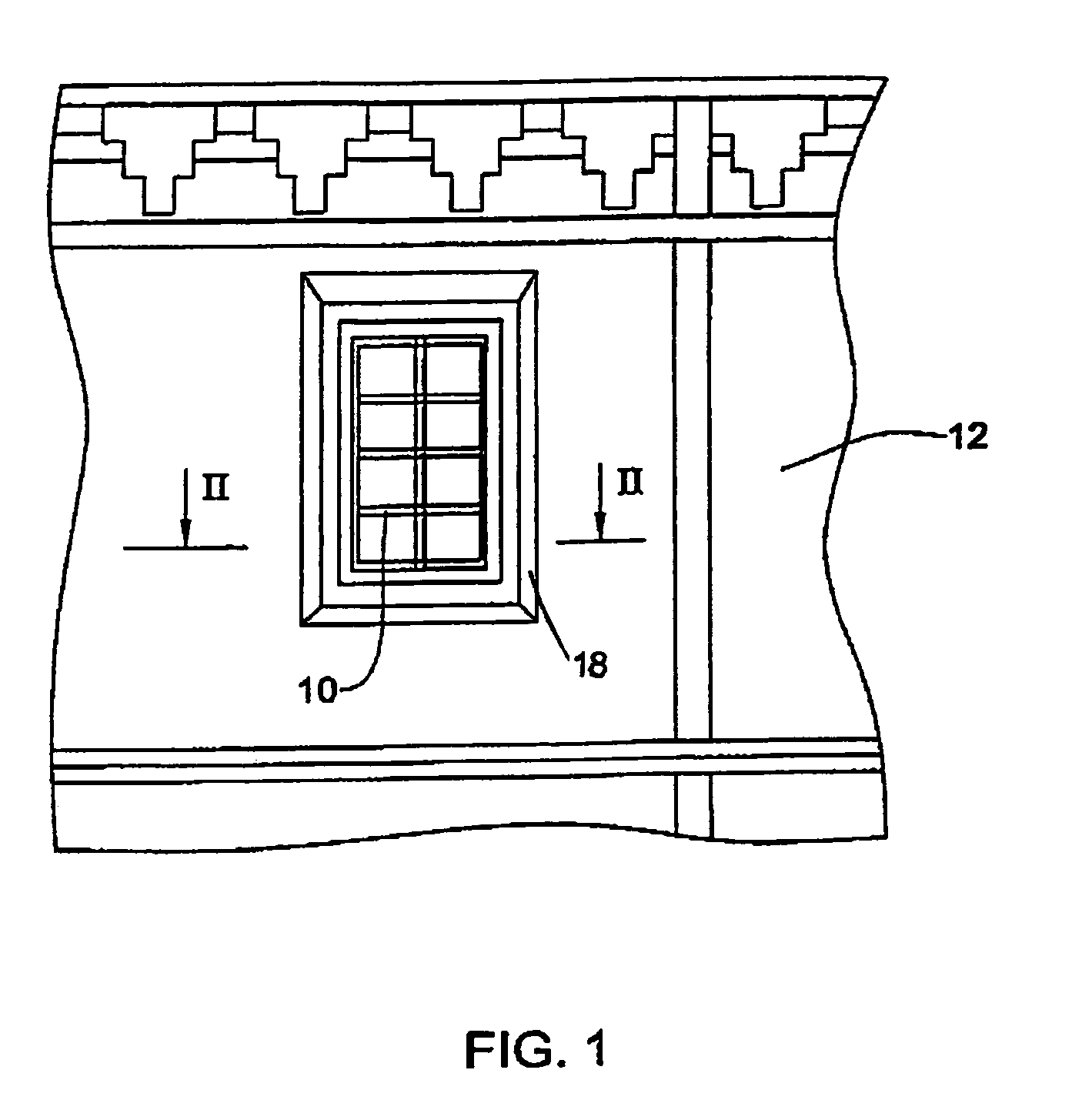
[0021]Turning first to FIG. 1 of the drawings, there is illustrated a front view of a portion of a building, i.e. from the outside, fitted with a so-called historic window designated 10, e.g. a window which has been declared as a conservation monument, in itself, or as part of the building 12, The window 10 is schematically illustrated in FIG. 2 and is supported within an opening 16 of the wall by means of a frame 18.

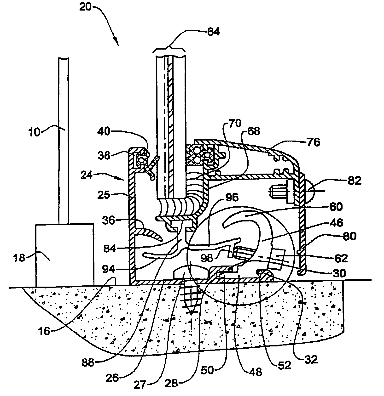
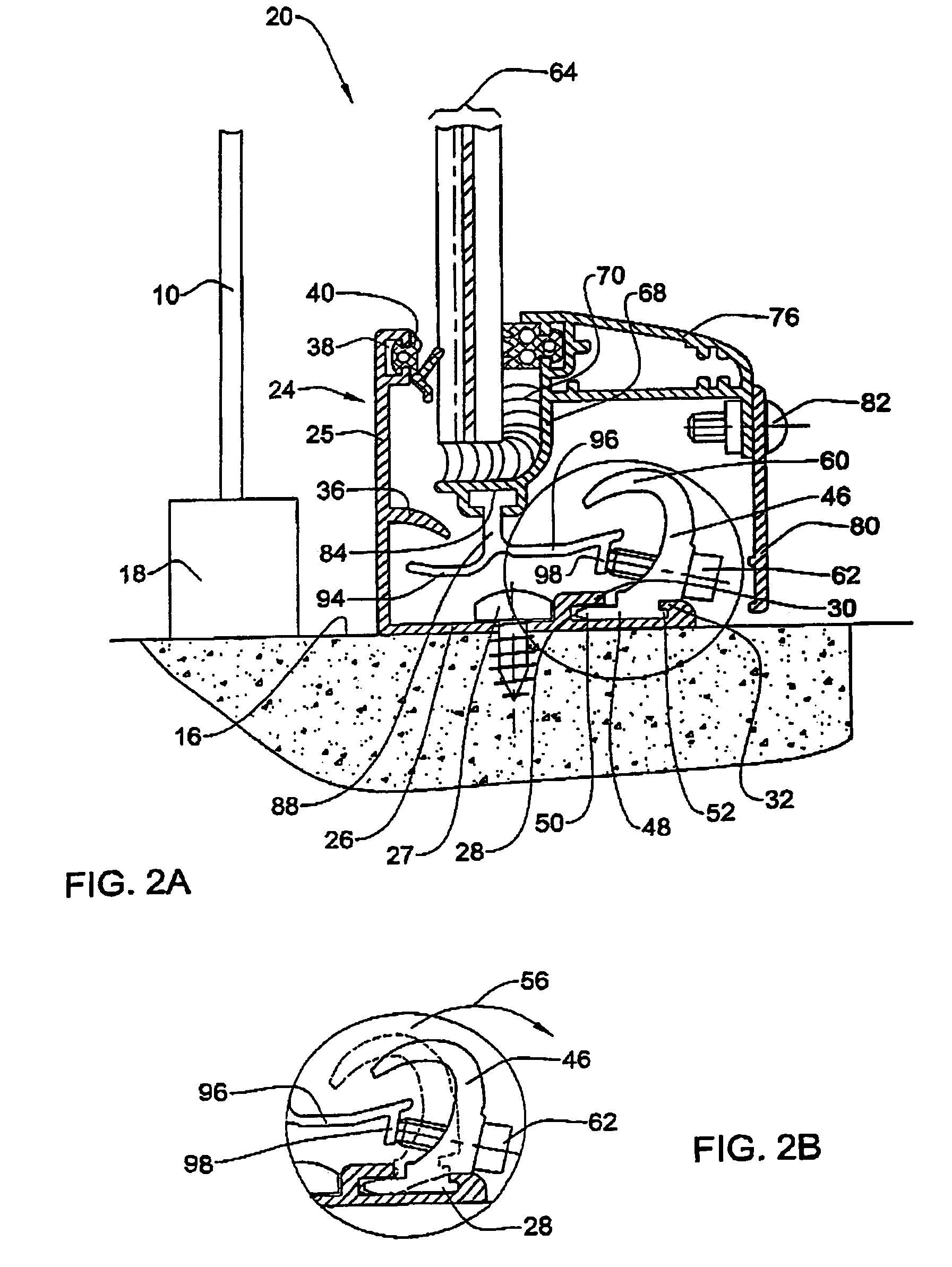
[0022]When it becomes necessary to install a reinforced window system generally designated 20, a frame 24 having a general inverted L-like shape with a first arm 25 and a second arm 26, is fitted within an opening 16 by means of bolts 27. In the present embodiment, frame 24 is entirely received within opening 16 though it will be appreciated that in other cases the frame may be partially fitted within the opening 16 and partially extending into the room space or, when there is only limited space at the opening, the frame 24 may be fitted on an inside portion of the wall...


PUM


Abstract

A reinforced window system for mounting within an opening in a wall, the window system comprising a frame fixable to the wall and a second frame, which is removably installable in the first frame. The first frame is provided with a plurality of fixing members distributed on the inside perimeter of the first frame. The second frame carries a reinforced window pane. The second frame is provided with a plurality of support members distributed on an outside perimeter of the second frame with possibility to face the fixing members of the first frame so as to support the second frame when the support members are in engagement with the fixing members of the first frame.

Description

FIELD OF THE INVENTION[0001]This present invention is in the field of protective window systems providing improved protection for individual and equipment preset within a protected space or structure. In particular, the invention is concerned with a blast resistant window system which may be easily removed, e.g. for cleaning and maintenance, and reinstalled in a foolproof manner.[0002]One particular use of such a window system is, for example, for use in preservation buildings wherein it is desired to maintain the original windows and nevertheless provide a blast resistant window protection system. Other use of such systems is for retrofit at any desired window opening.[0003]The term “window” as used herein in the specification and claims refers to a variety of window types, e.g. swingable, tiltable casement windows, fixed windows, curtain walls, etc.BACKGROUND OF TIE INVENTION[0004]It is an ever-growing trend by different authorities that old buildings and monuments be preserved so...

Claims


Application Information

Patent Timeline
Patent Type & Authority Patents(United States)
IPC IPC(8): E06B1/36E06B1/56E06B1/60E06B1/02E06B5/12
CPCE06B1/02E06B5/12E06B1/6046
Inventor EMEK, MORDECHAY
Owner ARPAL ALUMINUM
Why Eureka
Try Eureka