MEMS safe arm device for microdetonation

Inactive Publication Date: 2006-05-09
THE UNITED STATES OF AMERICA AS REPRESENTED BY THE SECRETARY OF THE NAVY
View PDF9 Cites 26 Cited by
  • Summary
  • Abstract
  • Description
  • Claims
  • Application Information

AI Technical Summary

Benefits of technology

[0009]Another embodiment of the present invention includes a method for utilizing a MEMS safe arm device for microdetonation including providing a safe arm device as discussed above; operating the lockpin inductor to affect the movement of the lockpin to retract from the set of safe indentations,

Problems solved by technology

Conventional mechanical safe-arm devices (MSADs) employing interrupted explosive trains are relatively large & heavy, typically the size of a 12-ounce soda can and weighing several pounds.
They are much too large for use in submunitions or micro “new tech” weapons.
However, ESADs, being exclusively electr

Method used


Image

  • MEMS safe arm device for microdetonation
  • MEMS safe arm device for microdetonation
  • MEMS safe arm device for microdetonation

Examples


Embodiment Construction

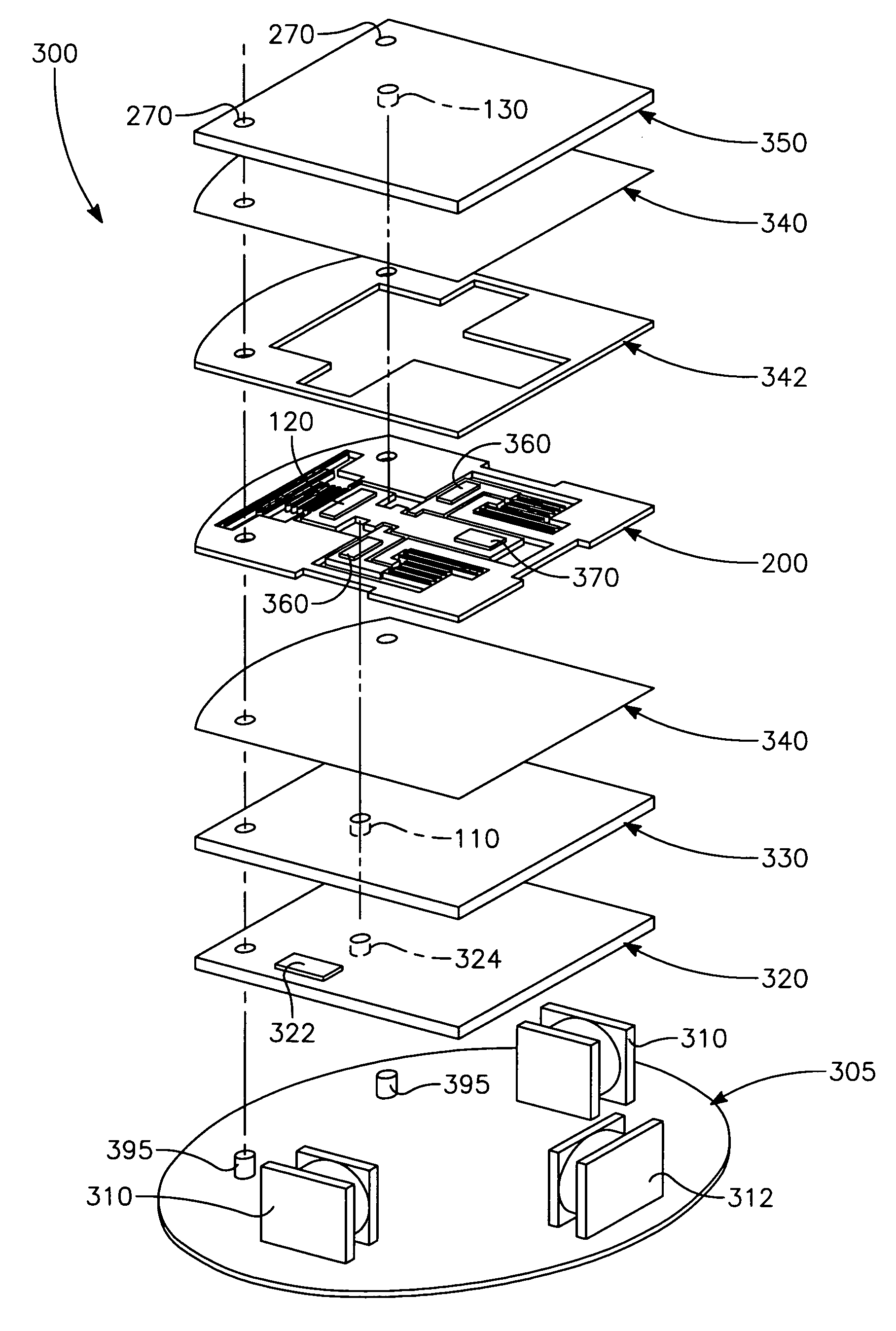
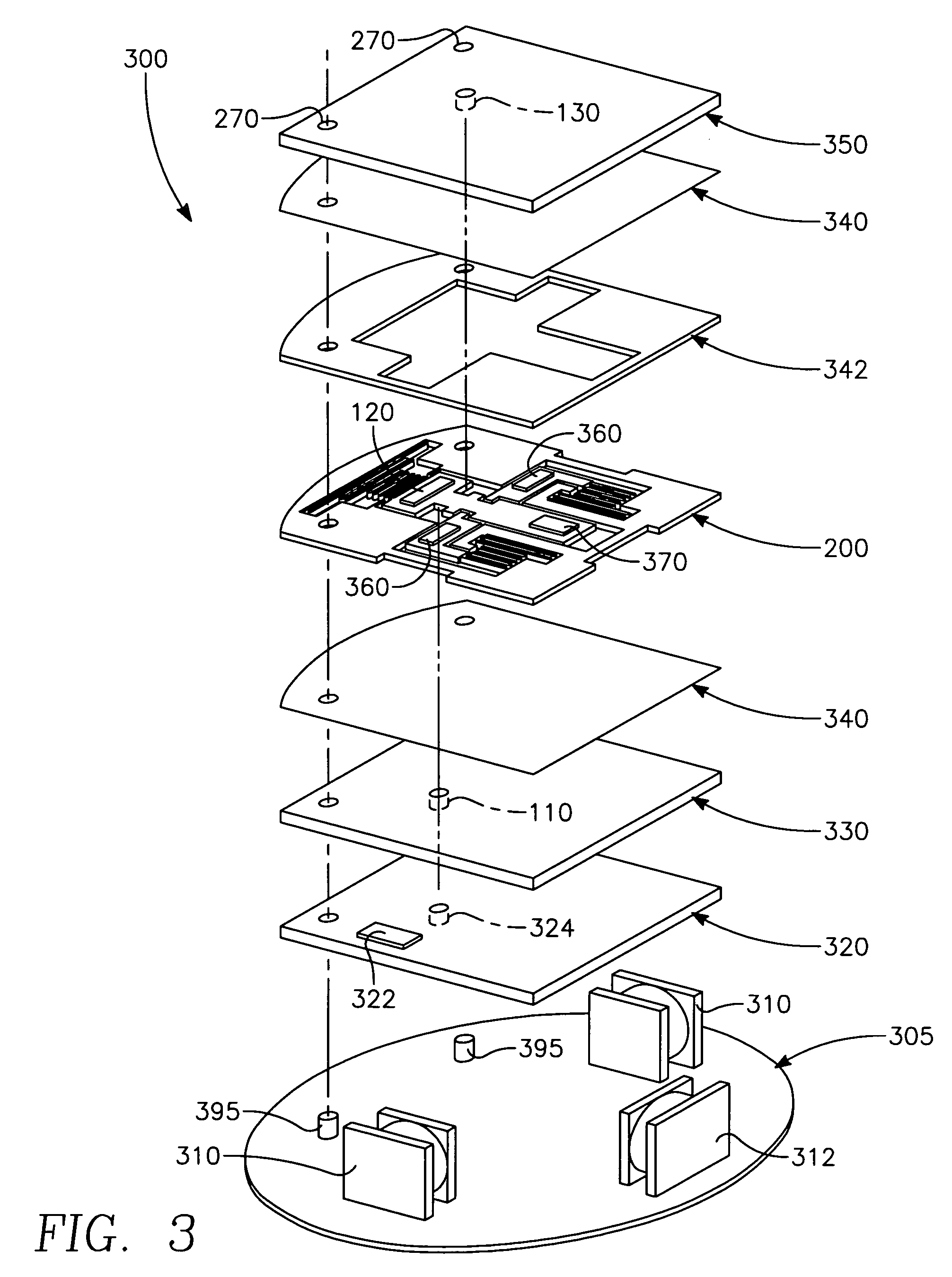
[0015]Embodiments of the present invention include a device and method for electronically arming an interrupted explosive train to detonate a main charge explosive. It should be understood that the examples and embodiments described herein are for illustrative purposes only and that various modifications or changes in light thereof will be suggested to persons skilled in the art and are to be included within the spirit and purview of this application and the scope of the appended claims.

Interrupted Explosive Train

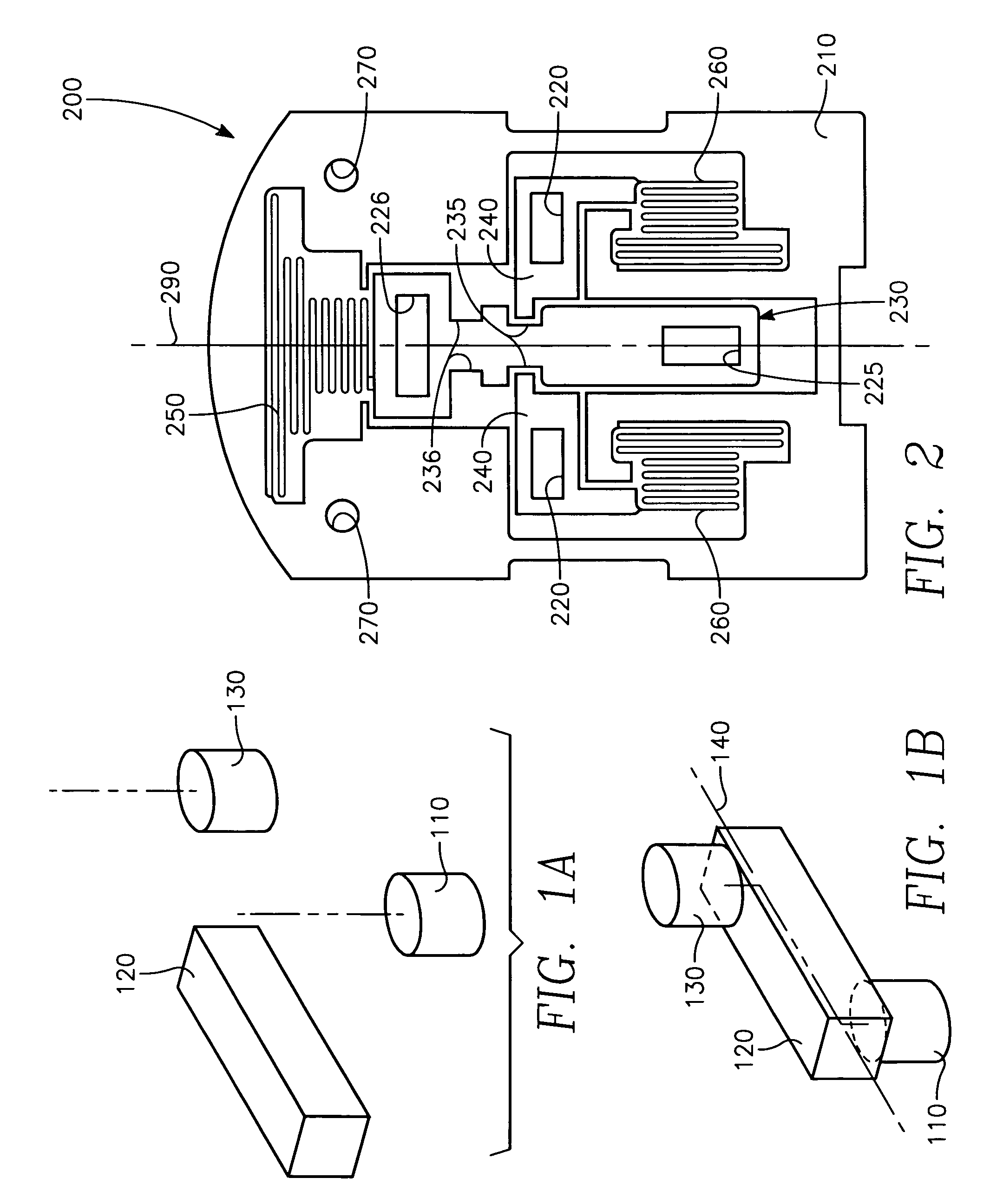
[0016]Referring to the drawings, wherein elements are identified by numbers and like elements are identified by like numbers throughout the figures, FIGS. 1A and 1B illustrate safe and armed positions of an interrupted explosive train according to embodiments of the present invention. As shown in FIG. 1A (in the safe position), the input charge 110 is physically separated and misaligned from the output charge 130, preventing the output charge 130 from detonating in the even...


PUM


Abstract

The present invention relates to a device for electronically arming and firing a MEMS-scale interrupted explosive train to detonate a main charge explosive. The device includes a MEMS slider assembly housing a transfer charge electrically actuated to move between safe and armed positions of the explosive train.

Description

CROSS-REFERENCE TO RELATED APPLICATIONS[0001]This application is co-pending and was concurrently filed with U.S. patent application having Navy Case No. 96531.STATEMENT REGARDING FEDERALLY SPONSORED RESEARCH OR DEVELOPMENT[0002]The invention described herein may be manufactured and used by or for the government of the United States of America for governmental purposes without the payment of any royalties thereon or therefor.FIELD OF THE INVENTION[0003]The present invention relates generally to safe and arm devices and more particularly to microelectromechanical systems (MEMS) safe and arm (also known as “safe arm”) devices for electrically arming an interrupted microexplosive train to detonate a main charge explosive.BACKGROUND OF THE INVENTION[0004]The primary purpose of a safe and arm device is to prevent accidental functioning of a main charge of explosive (military or otherwise) prior to arming, and to allow an explosive train of smaller charges to detonate the main charge after...

Claims


Application Information

Patent Timeline
IPC IPC(8): F42C15/18
CPCF42C15/184
Inventor MAURER, WALTER H.SOTO, GABRIEL H.HOLLINGSWORTH, DAVID R.
Owner THE UNITED STATES OF AMERICA AS REPRESENTED BY THE SECRETARY OF THE NAVY
Why Eureka
Try Eureka