Supercharge Your Innovation With Domain-Expert AI Agents!

Temperature-controlled fan delayed shut-off

a technology of temperature control and fan, which is applied in the direction of nailing tools, manufacturing tools, machines/engines, etc., can solve the problems of inability to produce uniform driving force for the driving of fastening elements, and achieve the effect of short time, satisfactory flushing of residual gases, and increased fan speed

Active Publication Date: 2006-05-09
HILTI AG
View PDF5 Cites 21 Cited by
  • Summary
  • Abstract
  • Description
  • Claims
  • Application Information

AI Technical Summary

Benefits of technology

[0011]Accordingly, the invention envisages setting the running time and / or the speed of the fan depending on a measured temperature. In this fashion, the advantage is provided that the fan runs for a longer time and / or at a faster speed only when a preset temperature is exceeded, as necessary.
[0012]At low temperatures, the fan is prevented from excessively cooling the combustion chamber by supplying cold fresh air. When this is done, either the running time alone or the speed of the fan alone can be set. Both the running time and the speed of the fan, however, can also be set.
[0014]In an advantageous embodiment of the invention an external temperature is measured using a second temperature sensor. In this fashion it is possible, with an increase of the external temperature, to set the fan for a longer cooling period or to increase the speed of the fan and thus to timely counter overheating of the combustion chamber.
[0015]The measured combustion chamber temperature is sent to a control unit, which regulates the cooling period and / or the motor speed of the fan as a factor of the measured combustion chamber temperature and / or the external temperature. By virtue of the capability of setting the time that the fan runs or the r.p.m. at which the fan runs in a pre-defined time unit, cooling can be limited at correspondingly low external temperatures or can be increased at correspondingly higher temperatures. In particular because the speed at which the motor of the fan operates can be set, satisfactory flushing of the residual gases can be achieved in a short time at high speed and, if required, the necessary cooling of the combustion chamber done. Accordingly, by increasing the speed at high combustion chamber temperatures a high setting rate is possible using the working tool.
[0016]In a further advantageous embodiment of the invention, the fan is arranged in the combustion chamber. This has the advantage, that utilization of the fan by the direct arrangement in the combustion chamber is very effective and consequently a costly air conduction system is eliminated, which would be needed to conduct the air flow generated by the fan arranged outside of the combustion chamber to the combustion chamber. The arrangement inside the combustion chamber requires a robust fan, which is not impaired in its functionality by the ignition processes.

Problems solved by technology

In an overly cooled combustion chamber, an optimum mixture of gases cannot be formed at the next ignition process and consequently a uniform driving force for driving the fastening elements cannot be produced.

Method used


Image

  • Temperature-controlled fan delayed shut-off
  • Temperature-controlled fan delayed shut-off
  • Temperature-controlled fan delayed shut-off

Examples


Embodiment Construction

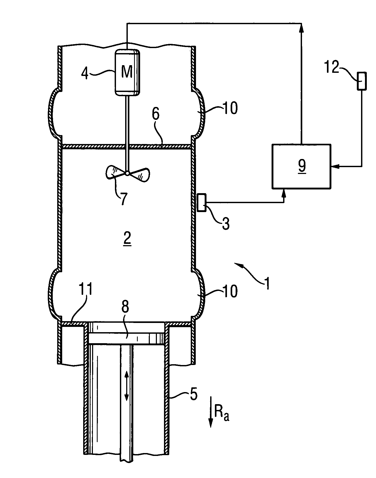
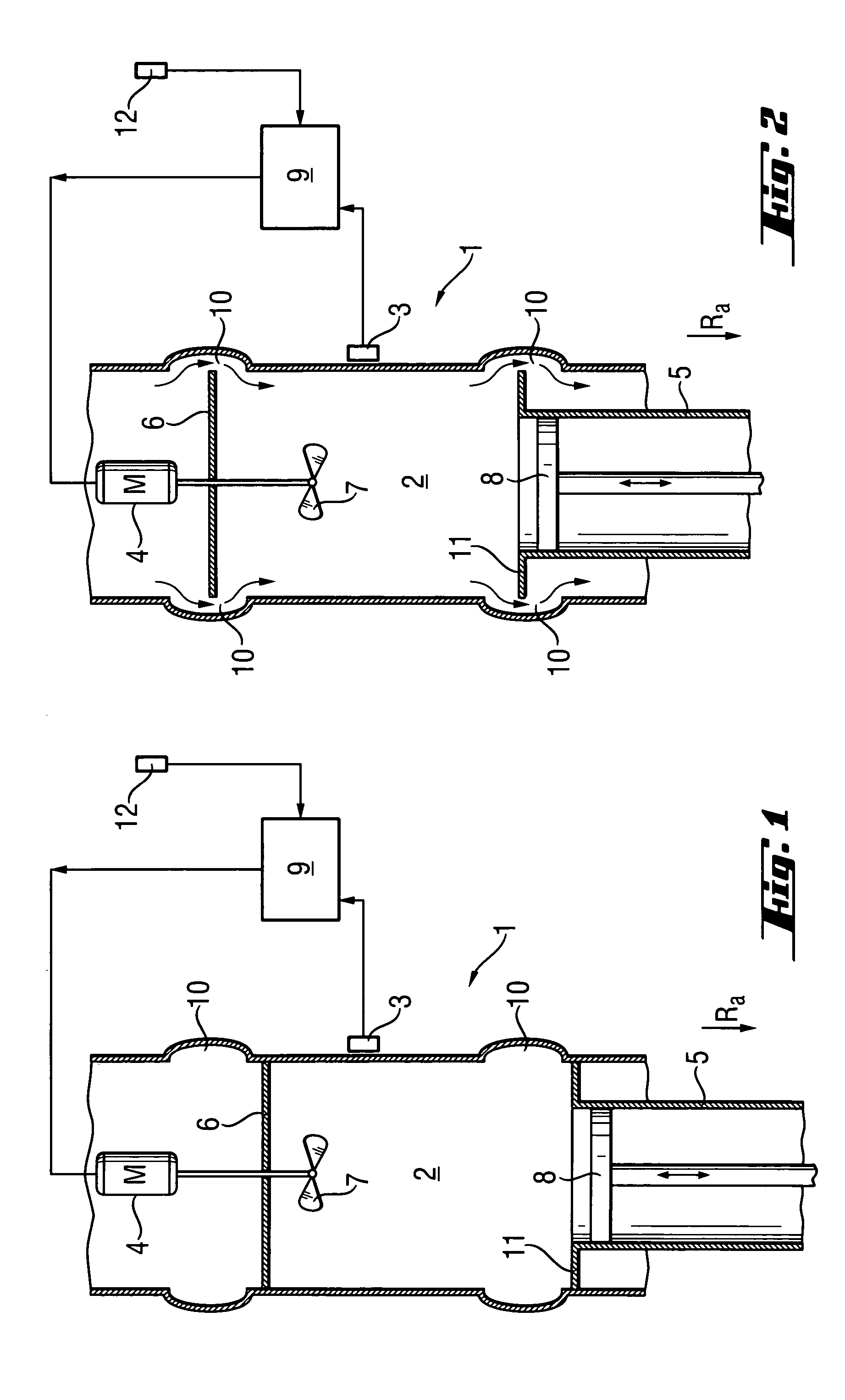
[0022]FIG. 1 shows a sectional view of a combustion driven working tool 1 having a combustion chamber 2. A mixture of fuel gases ready in the combustion chamber 2 is ignited by an ignition device (not shown), whereby the piston 8 coupled to the combustion chamber and guided in the cylinder 5 is driven in a working direction Ra. A fan 7 is arranged in the combustion chamber2 and serves to thoroughly mix the supplied mixture of gases and / or the supplied air and / or for cooling or flushing the combustion chamber. The fan 7 is driven by the motor 4. An upper combustion chamber wall 6 and a lower combustion chamber wall 11 are represented in a position, in which they approximately seal the outer walls of the combustion chamber 2, so that the combustion chamber is closed, for example before an ignition process.

[0023]A first temperature sensor is associated with the combustion chamber 2. This first temperature sensor 3 measures the combustion chamber temperature. A second temperature sensor...


PUM


Abstract

The invention relates to a combustion driven working tool having a combustion chamber (2), a piston (8) guided in a cylinder (5), an ignition system for igniting a fuel supplied to the combustion chamber (2) for driving the piston (8) and a fan (7) at least for ventilating the combustion chamber (2). The running time and / or the speed of the fan (7) can be set as a factor of a measured temperature to realize a combustion driven working tool where an optimal ignition behavior can be set under changing working conditions, in particular under conditions of changing external temperature. A combustion chamber temperature is measured by a first temperature sensor (3) arranged on the combustion chamber (2) and supplied to a control unit (9), which calculates the cooling time and / or the speed for the fan (7) as a factor of the measured combustion chamber temperature and supplies these values to the motor (4). A second temperature sensor (12) is utilized for measuring the external temperature for the calculation of the cooling time or the speed of the fan (7).

Description

BACKGROUND OF THE INVENTION[0001]The invention relates to an internal combustion driven working tool, in particular a setting tool for fastening elements, having a combustion chamber, a piston guided in a cylinder, an ignition system for igniting a fuel supplied to the combustion chamber for driving the piston and a fan at least for ventilating the combustion chamber, wherein the running time and speed of the fan can be set as a factor of a measured temperature.[0002]Internal combustion driven working tools are used for driving bolts or nails into substrates. These working tools have a combustion chamber into which a fuel is supplied. The fuel can be a transferred mixture of gases or a liquid gas, which is mixed in the combustion chamber with fresh air. The fuel can, however, also be provided in powder form as when installing a cartridge. A cylinder, into which a piston is guided, communicates with the combustion chamber. The piston is driven into the cylinder by igniting the fuel p...

Claims


Application Information

Patent Timeline
Patent Type & Authority Patents(United States)
IPC IPC(8): F02B71/00B25C1/08
CPCB25C1/08
Inventor GRANACHER, THOMASBUCHEL, FRANZSCHIESTL, ULRICH
Owner HILTI AG
Features
  • R&D
  • Intellectual Property
  • Life Sciences
  • Materials
  • Tech Scout
  • Unparalleled Data Quality
  • Higher Quality Content
  • 60% Fewer Hallucinations
Learn More