Measuring device for detecting a rotation angle in a contactless manner

a technology of measuring device and rotation angle, which is applied in the direction of instruments, galvano-magnetic hall-effect devices, galvano-magnetic devices, etc., can solve the problem of unnecessary comparison of compensation curves and complicated comparisons with known measuring instruments

Inactive Publication Date: 2006-05-09
ROBERT BOSCH GMBH
View PDF11 Cites 1 Cited by
  • Summary
  • Abstract
  • Description
  • Claims
  • Application Information

AI Technical Summary

Benefits of technology

[0007]The instrument according to the invention for contactless detection of an angle of rotation has the advantage over this prior art that the two linear regions of the measurement curves of the two sensitive faces can be combined to form one continuous linear region extending up to an angle of 360°. Despite these large angular ranges, the measuring instrument of the invention is very small, and because of its simple design, it is economical.
[0009]In a preferred exemplary embodiment of the present invention, the two sensitive Hall faces are disposed in the same plane. For simple positioning of the Hall element, the measurement signals of the two sensitive faces are carried away separately. Among other things, the positioning of the two sensitive Hall faces is also facilitated since the two faces, without compensation but with the same supply of current and the same influence of a magnetic field, would have to furnish the same results. This is true above all for the positions shown in FIGS. 3 and 4. To this extent, a complicated comparison with a compensation curve, as in the known measuring instruments, is unnecessary.
[0011]Preferably, the magnet is embodied in planar form and is disposed parallel to a plane that passes through the axis of the rotor. On the one hand, this makes a homogeneous magnetic field relative to the magnetically sensitive element possible, and on the other, it makes for insensitivity to axial offset and fluctuations in tolerances thereof.
[0014]Finally, in a preferred embodiment of the present invention, the evaluation of the output signals of the two sensitive faces is effected by means of a comparison algorithm, by which at every instant, the position of the object to be measured can be ascertained in a simple form.

Problems solved by technology

To this extent, a complicated comparison with a compensation curve, as in the known measuring instruments, is unnecessary.

Method used


Image

  • Measuring device for detecting a rotation angle in a contactless manner
  • Measuring device for detecting a rotation angle in a contactless manner
  • Measuring device for detecting a rotation angle in a contactless manner

Examples


Embodiment Construction

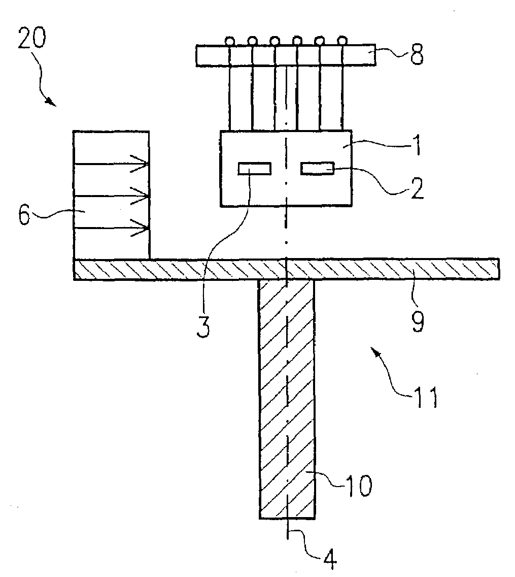
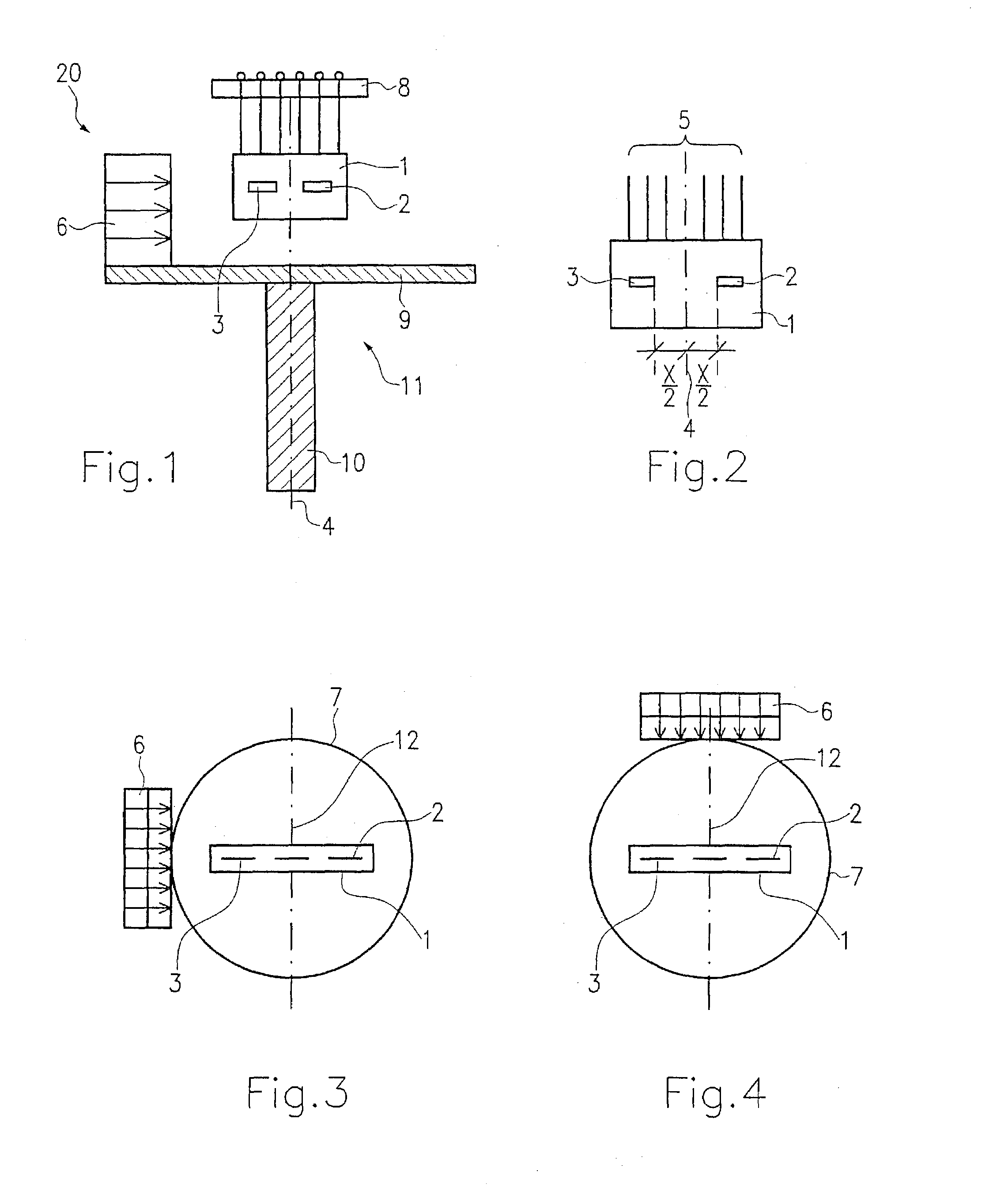
[0024]In the drawings, 20 indicates a sensor, which is connected with the aid of a shaft 10 to a component, not shown, whose rotary motion is to be determined. A carrier plate 9 which together with the shaft 10 acts as a rotor 11 is mounted centrally on the face end of the shaft 10. At least the carrier plate 9 and in particular the shaft 10 as well comprise magnetically nonconductive material. The carrier plate 9 is embodied as a circular disk. Spaced apart from the center point of the carrier plate 9 and from the center line 4 of the shaft 10, a permanent magnet 6 is secured, for instance to the edge of the carrier plate 9, as shown in FIGS. 1, 3 and 4. The permanent magnet 6 is embodied in planar form; that is, it has no curved shape that would conform to the circular shape of the carrier plate 9.

[0025]The permanent magnet 6 is disposed parallel to the axis 4 of the shaft 10. The polarization of the permanent magnet 6 is oriented perpendicular to the axis 4. Instead of a circular...


PUM


Abstract

A measuring instrument for contactless detection of an angle of rotation comprises a magnetically nonconductive rotor, on which a magnet is disposed, and a stationary magnetically sensitive element for generating a measurement signal. The magnetically sensitive element has two sensitive faces spaced apart by a distance.

Description

CROSS-REFERENCE TO RELATED APPLICATIONS[0001]This application is a 35 USC 371 application of PCT / DE 01 / 00451, filed on Feb. 06, 2001.BACKGROUND OF THE INVENTION[0002]1. Field of the Invention[0003]The invention is directed to an improved measuring instrument for contactless detection of an angle of rotation including a magnetically nonconductive rotor supporting a magnet and a stationary magnetically sensitive element for generating a measurement signal.[0004]2. Description of the Prior Art[0005]In one known measurement instrument described for example in DE 197 53 775.8 A1, flux conducting parts of magnetically conductive material have been used, among other elements, for orienting the lines of magnetic flux. However, this makes these measuring instruments relatively large, and only conditionally can they be built into measurement systems. Also, in this embodiment, it is not possible to vary the slope of the linear portions of the measurement curve sufficiently.[0006]To overcome th...

Claims


Application Information

Patent Timeline
Patent Type & Authority Patents(United States)
IPC IPC(8): G01B7/30G01D5/14G01D5/16
CPCG01D5/145
Inventor REICHL, ASTAKLOTZBUECHER, THOMAS
Owner ROBERT BOSCH GMBH
Why Eureka
Try Eureka