Plethysmograph pulse recognition processor

a plethysmograph and processor technology, applied in the field of plethysmograph pulse recognition processors, can solve the problems of complex task, noise-induced plethysmographic waveforms,

Inactive Publication Date: 2006-05-16
JPMORGAN CHASE BANK NA
View PDF112 Cites 870 Cited by
  • Summary
  • Abstract
  • Description
  • Claims
  • Application Information

AI Technical Summary

Problems solved by technology

However, this task is complicated, even under ideal conditions, by the variety of physiological plethysmographic waveforms.
Further, plethysmographic waveforms are often corrupted by noise, including motion artifact, as described in U.S. Pat. No. 2,632,272 cited above.

Method used


Image

  • Plethysmograph pulse recognition processor
  • Plethysmograph pulse recognition processor
  • Plethysmograph pulse recognition processor

Examples


Embodiment Construction

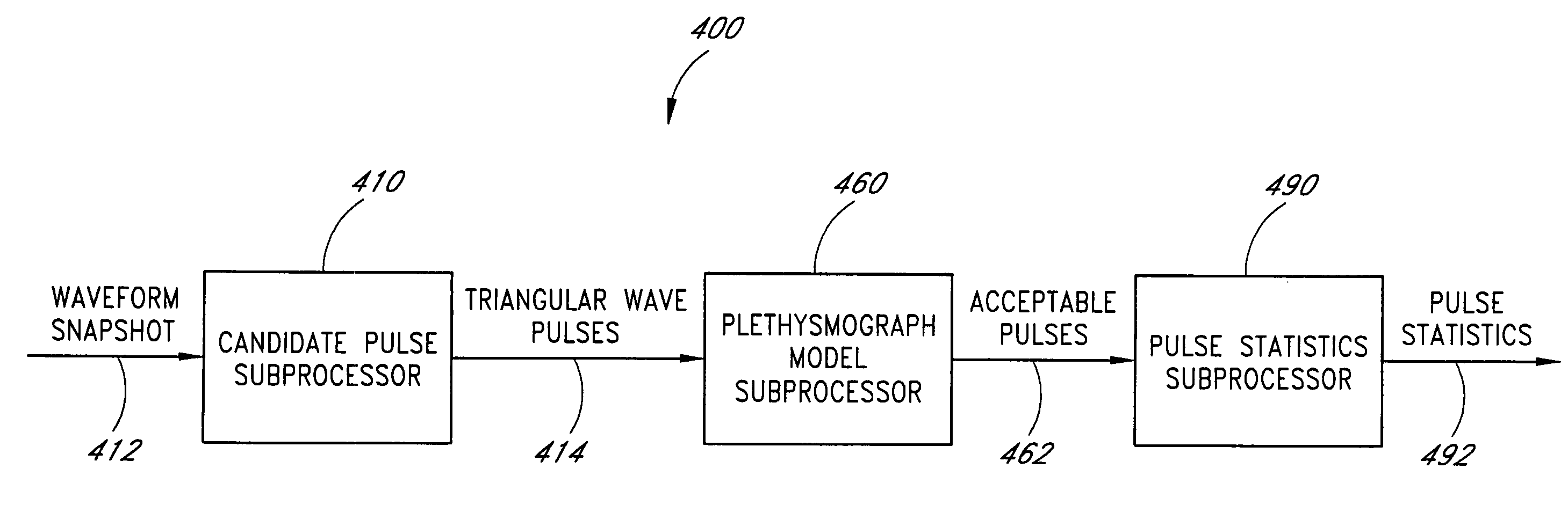
[0034]FIG. 4 illustrates the plethysmograph pulse recognition processor 400 according to the present invention. The pulse processor 400 has three subprocessors, a candidate pulse subprocessor 410, a plethysmograph model subprocessor 460, and a pulse statistics subprocessor 490. The candidate pulse subprocessor 410 applies various waveform criteria or “edge checks” to find candidate pulses in an input waveform “snapshot”412. In a particular embodiment, the snapshot is 400 samples of a detected intensity plethysmograph taken at a 62.5 Hz sampling rate. This snapshot represents a 6.4 second waveform segment. The output 414 of the candidate pulse subprocessor 410 is peaks and valleys of the input waveform segment representing a triangular wave model of identified candidate pulses. The candidate pulse output 414 is input to the plethysmograph model subprocessor 460, which compares these candidate pulses to an internal model for physiological pulses. The output 462 of the plethysmograph m...


PUM

PropertyMeasurementUnit
thresholdaaaaaaaaaa
thresholdaaaaaaaaaa
pulse frequencyaaaaaaaaaa

Abstract

A time domain rule-based processor provides recognition of individual pulses in a pulse oximeter-derived photo-plethysmograph waveform.

Description

REFERENCE TO RELATED APPLICATION[0001]The present application claims priority benefit under 35 U.S.C. § 120 to, and is a continuation of U.S. patent application Ser. No. 10 / 267,446, filed Oct. 8, 2002 now U.S. Pat. No. 6,818,741, entitled “Plethysmograph Pulse Recognition Processor,” which is a continuation of U.S. patent application Ser. No. 09 / 471,510, filed Dec. 23, 1999, entitled “Plethysmograph Pulse Recognition Processor,” now U.S. Pat. No. 6,463,311, which claims priority benefit under 35 U.S.C. § 119(e) from U.S. Provisional Application No. 60 / 114,127, filed Dec. 30, 1998, entitled “Plethysmograph Pulse Recognition Processor.” The present application also incorporates the foregoing utility disclosure herein by reference.BACKGROUND OF THE INVENTION[0002]Oximetry is the measurement of the oxygen status of blood. Early detection of low blood oxygen is critical in the medical field, for example in critical care and surgical applications, because an insufficient supply of oxygen ...

Claims


Application Information

Patent Timeline
Patent Type & Authority Patents(United States)
IPC IPC(8): A61B5/02A61B5/00G01N21/27A61B5/024A61B5/0245G01N21/35
CPCA61B5/02416A61B5/14551A61B5/7264
Inventor DIAB, MOHAMED K.
Owner JPMORGAN CHASE BANK NA
Why Eureka
Try Eureka