
Applicator for high-speed gel buffering of flextube optical fiber bundles

a technology of optical fiber bundles and gel buffers, applied in the field of fiber optic cables, can solve the problems of numerous drawbacks of techniques, inconsistent coating of fibers, and degradation of information transmission ability, and achieve the effect of improving the quality of optical fiber cables

Inactive Publication Date: 2006-05-16
DRAKA COMTEQ BV
View PDF20 Cites 145 Cited by
  • Summary
  • Abstract
  • Description
  • Claims
  • Application Information

AI Technical Summary

Benefits of technology

The present invention aims to resolve issues associated with applying water barrier fluids to optical fibers and bundles. It improves the quality of the optical fiber cable and the manufacturing process used to apply the gel.

Problems solved by technology

The technical problem addressed in this patent text is the need for an improved apparatus for applying gel to optical fibers in order to prevent degradation caused by water and humid air, while overcoming the drawbacks of existing methods such as inconsistent coating and air entrapment.

Method used


Image

  • Applicator for high-speed gel buffering of flextube optical fiber bundles
  • Applicator for high-speed gel buffering of flextube optical fiber bundles
  • Applicator for high-speed gel buffering of flextube optical fiber bundles

Examples


Embodiment Construction

[0020]The present invention will be explained in further detail by making reference to the accompanying drawings, which do not limit the scope of the invention in any way.

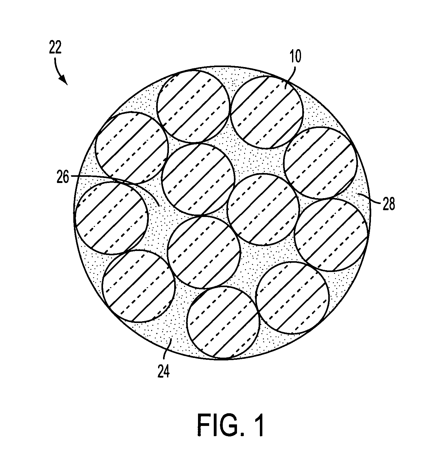
[0021]With reference to FIG. 1, a plurality of optical fibers 10 are shown in a radial arrangement forming a fiber bundle 22. In this embodiment, twelve optical fibers 10 are shown; however, it will be appreciated that the optical fiber bundle 22 may consist of a varying arrangement and number of optical fibers 10. The fiber bundle 22 is shown as having an outer portion 24 and an inner portion 26.

[0022]According to the present invention, a water barrier fluid 28, for example, a thixotropic gel, is disposed onto the outer 24 and inner 26 portions of the fiber bundle 22, as described below. The gel 28 acts to prevent ingress of water to the optical fiber surface produced from direct liquid contact or exposure to humid air. Although, thixotropic gel is described, any of a broad classification of fluid polymeric materi...


PUM

PropertyMeasurementUnit
Diameteraaaaaaaaaa
Speedaaaaaaaaaa
Circumferenceaaaaaaaaaa

Abstract

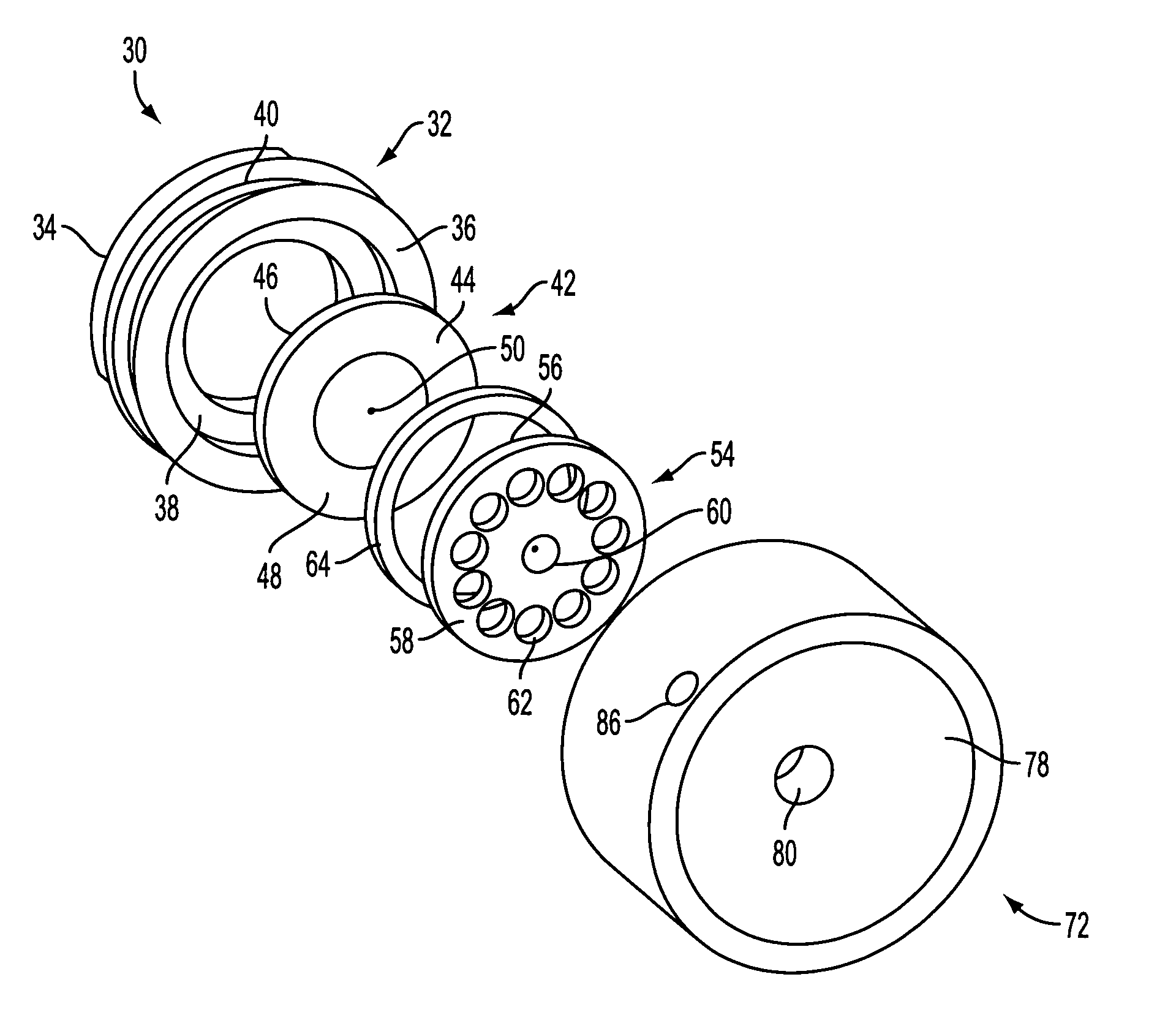
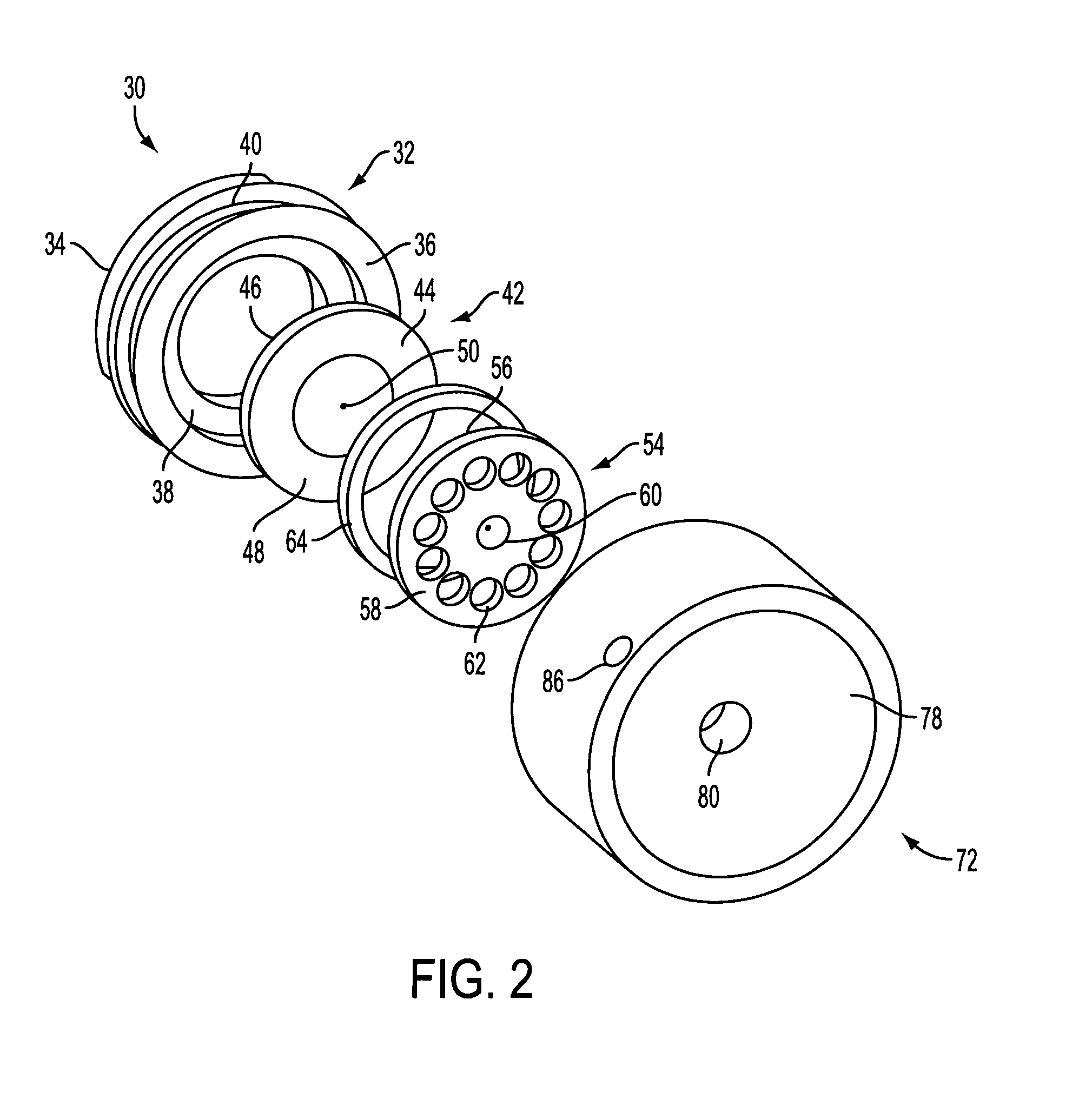
The present invention includes an apparatus for combining a water barrier fluid to a bundle of optical fibers including an entrance die having an orifice which is dimensioned to allow for a bundle of optical fibers to be drawn therethrough. Also, an exit die having an orifice is provided. The entrance die and the exit die, respectively, have inner sides which define a cavity. The cavity is in fluid communication with the orifice of the entrance die and the orifice of the exit die, such that a gap is formed at a meeting point between the cavity and the respective orifices of the entrance and the exit die. The gap is radially surrounded by an extension of the cavity to define a critical flow region. A plurality of baffles are formed in the exit die which are operative to inject fluid into the cavity. Also provided is a main body which supports the entrance die and the exit die. The main body includes a passageway that is in fluid communication with the plurality of baffles. A retaining ring is included which secures the entrance die and the exit die to the main body.

Description


Claims


Application Information

Patent Timeline
Owner DRAKA COMTEQ BV
Learn More