Hydrocarbon synthesis process using pressure swing reforming

a hydrocarbon synthesis and reforming technology, applied in the direction of oxygen-containing compound preparation, sustainable manufacturing/processing, oxygen compound purification/separation, etc., can solve the problems of low productivity, limited economic attractiveness of the process, and excessive heat generation, and achieve the effect of thermal and material efficiencies over conventional reforming

Active Publication Date: 2006-05-16
EXXON RES & ENG CO
View PDF5 Cites 87 Cited by
  • Summary
  • Abstract
  • Description
  • Claims
  • Application Information

AI Technical Summary

Benefits of technology

[0018]The present invention, in one aspect, provides an improvement in exothermic hydrocarbon synthesis processes that use synthesis gas, in which the improvement comprises integrating pressure swing reforming with such a synthesis process whereby thermal and material efficiencies over conventional reforming are achieved. Thus is one embodiment at least some hydrogen which is produced in the pressure swing reforming process is removed from the synthesis gas and is combusted with air to provide the heat for the regeneration step of the pressure swing reforming process. In another embodiment the exothermic synthesis process is cooled with water to produce steam which is used in the pressure swing reforming.

Problems solved by technology

Unfortunately, steam reforming furnaces occupy a very large volume of space, orders of magnitude greater than the tube volume, such that low productivity limits the economic attractiveness of the process.
However, gas-phase reaction kinetics tend to over-oxidize some of the feed, resulting in excessive heat generation and substantial yield of H2O, CO2, and unreacted hydrocarbons that my leave the reactor as soot.
However, autothermal reforming requires a source of oxygen.
In the fuel cell vehicle case, this oxygen in typically provided as low-pressure air, which results in a nitrogen-diluted, low-pressure synthesis gas, while in refinery or chemicals embodiments, this oxygen is typically provided as purified O2, and the cost of air separation can be greater than the cost of the autothermal reforming process.
However, the examples and commercial projections within these patents describe a process that operates at very low productivity, with space velocities of around 95 hr−1 (as C1-equiv).

Method used


Image

  • Hydrocarbon synthesis process using pressure swing reforming
  • Hydrocarbon synthesis process using pressure swing reforming
  • Hydrocarbon synthesis process using pressure swing reforming

Examples


Embodiment Construction

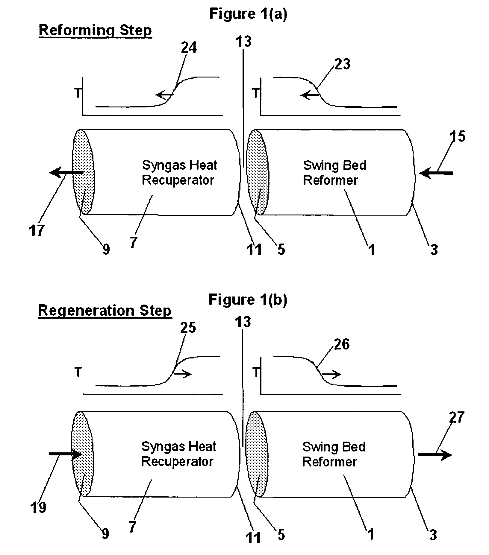
[0032]The basic two-step cycle of pressure swing reforming is depicted in FIG. 1. Referring now to FIGS. 1a and 1b, a first zone, or reforming zone (1), called a swing bed reformer, and a second zone, or recuperating zone, called a synthesis gas heat recuperator (7). The beds of both zones will include packing material, while the reforming bed (1) will include catalyst for steam reforming. Though illustrated as separate reforming and recuperating zones, it is to be recognized that the pressure swing reforming apparatus may comprise a single reactor.

[0033]As shown in FIG. 1a, at the beginning of the first step of the cycle, also called the reforming step, the reforming zone (1) is at an elevated temperature and the recuperating zone (7) is at a lower temperature than the reforming zone (1). A hydrocarbon-containing feed is introduced via a conduit (15), into a first end (3) of the reforming zone (1) along with steam. The hydrocarbon may be any material that undergoes the endothermic ...


PUM

PropertyMeasurementUnit
temperaturesaaaaaaaaaa
temperatureaaaaaaaaaa

Abstract

The invention provides a method for producing liquid hydrocarbons by first generating in a pressure swing reformer a synthesis gas stream having a mole ratio of H2:CO greater than 2:1. Then, a portion of the hydrogen is separated to produce a synthesis gas stream having a mole ratio of H2:CO of about 2:1 which steam is then introduced into a hydrocarbon synthesis reactor for conversion to liquid products.

Description

CROSS REFERENCE TO RELATED APPLICATION[0001]This application is a Continuation-in-Part of Non-Provisional application Ser. No. 10 / 756,651 filed Jan. 13, 2004 which is based on Provisional Application No. 60 / 450,902 filed Feb. 28, 2003.FIELD OF THE INVENTION[0002]The present invention relates to process improvements in synthesizing hydrocarbon compounds from synthesis gas. More particularly, the invention relates to a process scheme wherein synthesis gas is produced in a cyclic packed-bed operation in which the reforming cycle of the synthesis gas production is performed at a higher pressure than the regeneration cycle and in which light gas and steam from the hydrocarbon synthesis process is used in the reforming cycle.BACKGROUND OF THE INVENTION[0003]Conventional synthesis gas generating processes include steam reforming, gas phase partial oxidation and autothermal reforming. Each of these processes has advantages and disadvantages when compared to each other.[0004]In a steam refor...

Claims


Application Information

Patent Timeline
Patent Type & Authority Patents(United States)
IPC IPC(8): C07C27/00C01B3/38C01B3/46C07C29/151
CPCC01B3/38C10G2/32C07C29/1518C01B3/46C01B2203/00C01B2203/0233C01B2203/0405C01B2203/062C01B2203/0805C01B2203/0811C01B2203/0822C01B2203/0827C01B2203/0833C01B2203/0894C01B2203/1241C01B2203/148C01B2203/1619C01B2203/1676C01B2203/169C01B2203/1695C01B2203/80C01B2203/84Y02P20/10
Inventor HERSHKOWITZ, FRANK
Owner EXXON RES & ENG CO
Why Eureka
Try Eureka