Buckle

a buckle and buckle technology, applied in the field of buckles, can solve the problems of difficult release of buckles, increase in load, and difficulty in operation of release mechanisms, and achieve the effects of convenient latching and unlocking, improved strength, and efficient use of materials

Active Publication Date: 2008-06-12
ILLINOIS TOOL WORKS INC
View PDF8 Cites 29 Cited by
  • Summary
  • Abstract
  • Description
  • Claims
  • Application Information

AI Technical Summary

Benefits of technology

[0010]An advantage of the present invention, in one form thereof, is providing a two-piece buckle that latches and unlatches easily even when under load, but which resists unintended unlatching when load is applied to the buckle.
[0011]Another advantage of the present invention, in another form thereof, is providing a two-piece buckle that uses material efficiently in a buckle of improved strength.
[0012]Yet another advantage of the present invention, in yet another form thereof, is providing a buckle that fits together snuggly when latched, with minimal play between the buckle components even when not under load.
[0013]Other features and advantages of the invention will become apparent to those skilled in the art upon review of the following detailed description, claims and drawings in which like numerals are used to designate like features.

Problems solved by technology

Some buckles are difficult to release when under load.
When under load, this causes an increase in the load, and as a result, the release mechanism can be difficult to operate.
Accordingly, when latched but not under load, the male and female components may feel loosely fit one in the other and may even rattle or otherwise move one with respect to the other.
While such looseness may not affect overall performance of the buckle, the user may feel that the buckle is not secure.
This, then, can result in the aforementioned difficulty in releasing the buckle under load.

Method used


Image

  • Buckle
  • Buckle
  • Buckle

Examples


Embodiment Construction

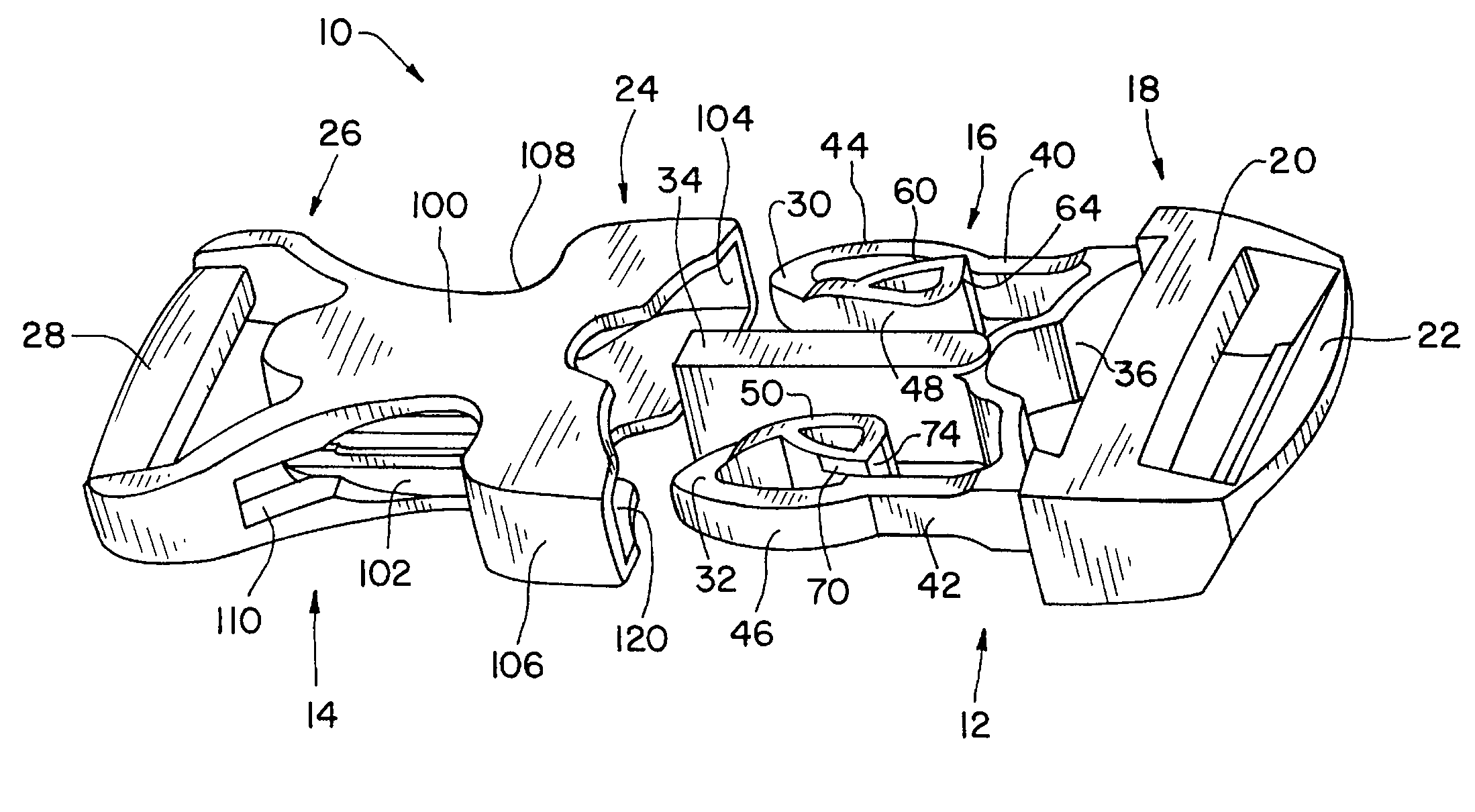
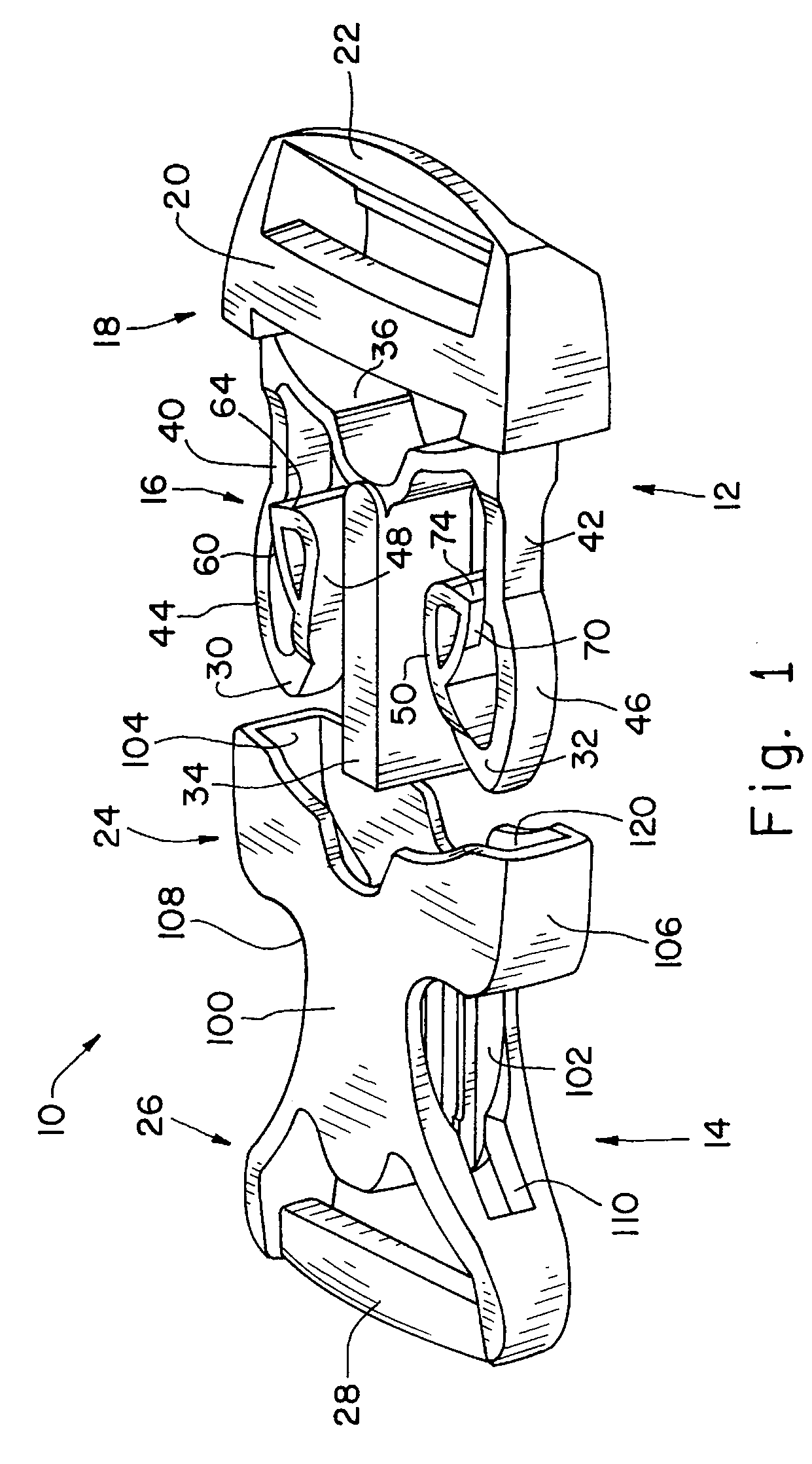
[0021]Referring now more specifically to the drawings and to FIG. 1 in particular, a buckle 10 in accordance with the present invention is shown. Buckle 10 includes a male component 12 and a female component 14. Male component 12 includes a latch 16 and a web attachment structure 18 including web bars 20 and 22. Female component 14 includes a receiving body or pocket 24 and a web attachment structure 26 including a web bar 28. Latch 16 is inserted into and received by pocket 24 of female component 14 whereby buckle 10 is latched. Male component 12 and female component 14 can be made as individual monolithic structures of plastic formed by injection molding processes, or the like.

[0022]Straps or webs (not shown) can be attached to web bars 20, 22 and 28 in known manner so that buckle 10 can be used to secure together opposite ends of a single web or to secure ends of separate webs. In the exemplary embodiment shown in FIG. 1, web bars 20 and 22 of male component 12 can receive a web ...


PUM


Abstract

A two-part buckle includes a male buckle component received in a female buckle component. Lock surfaces between the male and female buckle components are provided inwardly of flexible segments of the lock arms and axially between the flexible portion of the lock arm and accessible ends of the lock arms depressed for unlatching the buckle. The lock surfaces angle toward the disengaged positions in the direction of arm movement for unlatching.

Description

CROSS-REFERENCE TO RELATED APPLICATIONS[0001]The present regular United States patent application claims the benefits of United States Provisional Application for patent Ser. No. 60 / 874,443, filed on Dec. 12, 2006.FIELD OF THE INVENTION[0002]The present invention relates to two-part buckles that include a male component snapped into a female component, with release effected by squeezing accessible portions of the male component, to disengage the male component from a locked condition in the female component.BACKGROUND OF THE INVENTION[0003]Two-piece buckles that snap together and latch automatically upon adequately inserting a male component into a female component are known and used in a variety of applications. A piece of webbing or strap can be attached to each of the components, and one or both buckle components can be adjustably retained on the strap or webbing. It is also known to have both components in fixed locations relative to a strap or web that is sewn or otherwise fixe...

Claims


Application Information

Patent Timeline
Patent Type & Authority Applications(United States)
IPC IPC(8): A44B11/25
CPCA44B11/266Y10T24/45524Y10T24/45529Y10T24/45581
Inventor KOLASA, SCOTT D.PONTAOE, JOHN S.
Owner ILLINOIS TOOL WORKS INC
Why Eureka
Try Eureka