Vacuum cleaner capable of compressing dirt

a vacuum cleaner and dirt technology, applied in the field of vacuum cleaners, can solve the problems of affecting and the fibrous type dirt having a relatively small mass may not be easily separated, so as to achieve the effect of compressing dirt accumulated, preventing premature degradation of the suction performance of the vacuum cleaner due to a small amount of dirt, and reducing the amount of suction air flow

Inactive Publication Date: 2006-05-23
PANASONIC CORP
View PDF10 Cites 20 Cited by
  • Summary
  • Abstract
  • Description
  • Claims
  • Application Information

AI Technical Summary

Benefits of technology

[0005]It is, therefore, a primary object of the present invention to provide a vacuum cleaner capable of compressing the dirt that is centrifugally separated by the air flow drawn from a suction head and then is accumulated in a dirt collecting chamber, so that the suction efficiency of the vacuum cleaner is prevented from being prematurely deteriorated to thereby improve the suction efficiency and reduce the frequency of dumping dirt from the dirt collecting chamber.
[0010]With such a construction, it is possible to effectively compress dirt accumulated in the dirt collecting case, particularly dirt of a fibroid material and, therefore, premature degradation of the suction performance of the vacuum cleaner due to a small amount of dirt can be effectively prevented. Further, the convenience in using the vacuum cleaner can be enhanced.

Problems solved by technology

Therefore, if a large amount of fibroid material, e.g., cotton or the like, is included in the dirt containing air, thus separated dirt tends to occupy a large volume relative to its mass.
However, fibrous type dirt having a relatively small mass may not be readily separated from the dirty air in the centrifugal separation process of the cyclonic dirt collector and consequently may be readily stuck on a surface of the main filter, thereby decreasing the amount of suction air flow.
In other words, the suction efficiency of a vacuum cleaner can be rapidly deteriorated by the intake of air containing dirt having a relatively small mass.
Such a problem may be addressed by increasing the size of a dirt collector to accommodate a sufficient amount of dirt with a small mass; however, such would not be advantageous because increasing the volume of the dirt collector is not only cumbersome but also against the current trend for the smaller and lighter vacuum cleaners.

Method used


Image

  • Vacuum cleaner capable of compressing dirt
  • Vacuum cleaner capable of compressing dirt
  • Vacuum cleaner capable of compressing dirt

Examples


Embodiment Construction

[0022]A first preferred embodiment of the present invention will now be described in detail with reference to FIGS. 1 to 8.

[0023]Referring to FIG. 3, there is shown a perspective view of a vacuum cleaner 100 in accordance with the present invention. The vacuum cleaner 100 includes a main body (canister body) 1 having a hose joint 3; a hose 4 connected to the main body 1 via the hose joint 3; an extension tube 5 provided with a handle 2 and connected to the hose 4 at one of its ends; and a suction head 6, installed at a free end of the extension tube 5, for the intake of dirt entraining air, whereby the main body 1 is in air flow communication with the suction head 6. The vacuum cleaner 100 further includes a caster 7 at a front bottom portion of the main body 1 and a pair of wheels 8 at both sides of a rear bottom portion thereof.

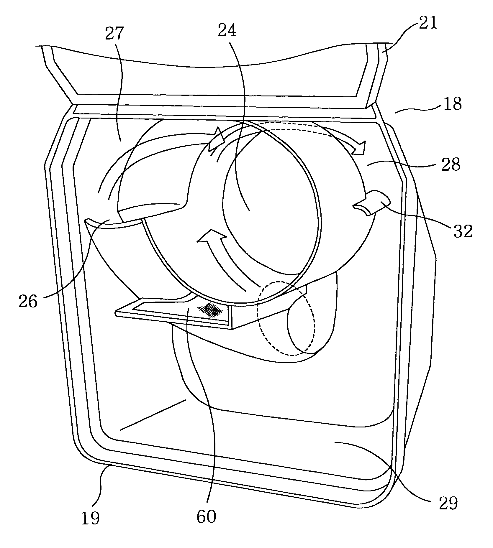
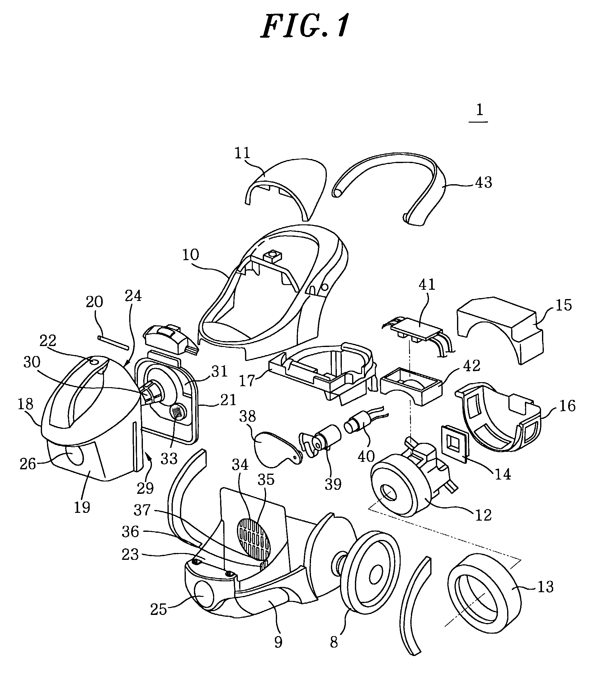
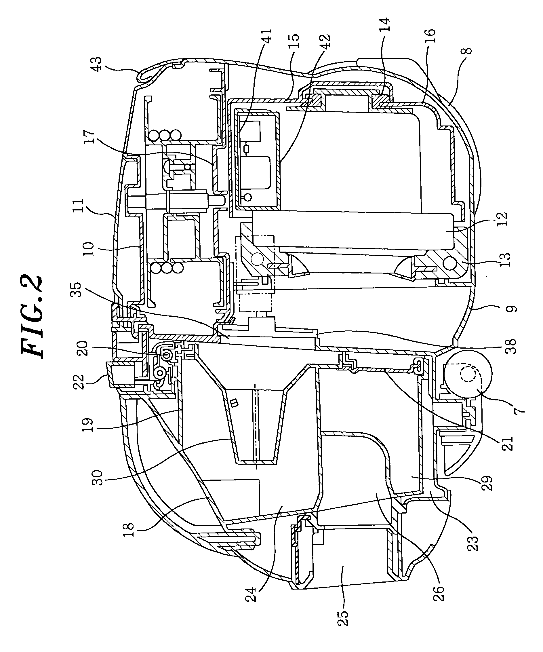
[0024]As shown in FIGS. 1 and 2, the main body 1 has a lower body 9, an upper body 10 and a cover 11 defining the outline thereof in conjunction with each ...


PUM

PropertyMeasurementUnit
timeaaaaaaaaaa
volumeaaaaaaaaaa
time periodaaaaaaaaaa

Abstract

A vacuum cleaner includes a main body having an electric blower for generating a suction air flow, a dirt collecting case for centrifugally separating and collecting dirt, and a compression assembly for compressing dirt collected in the dirt collecting case to reduce a volume thereof. The dirt collecting case has a separation chamber for centrifugally separating dirt from the dirt containing air and a dirt collecting chamber in communication with the separation chamber for accumulating the dirt separated by the separation chamber. The compression assembly has a first air intake member provided in the separation chamber and communicating with the electric blower, a second air intake member provided in the dirt collecting chamber and communicating with the electric blower, a shielding plate for selectively opening the first and the second air intake member and an actuator for driving the shielding plate.

Description

FIELD OF THE INVENTION[0001]The present invention relates to a vacuum cleaner; and, more particularly, to a vacuum cleaner incorporating therein a dirt collecting case (a cyclonic dirt collecting part) which centrifugally separates dirt by way of imparting a cyclonic flow to the suction air.BACKGROUND OF THE INVENTION[0002]In prior art vacuum cleaners equipped with such cyclonic dirt collectors as described in, e.g., Japanese Laid-Open Publication Nos. 2000-342492 and 1997-253011, dirt entraining air is separated into dirt and clean air by a cyclonic air flow in a cyclonic dirt collector and thus separated dirt then merely piles up at a lower portion of the cyclonic dirt collector.[0003]Therefore, if a large amount of fibroid material, e.g., cotton or the like, is included in the dirt containing air, thus separated dirt tends to occupy a large volume relative to its mass. In a dirt separating process, dirt with a large mass rotates along an outer peripheral side of the cyclonic dirt...

Claims


Application Information

Patent Timeline
Patent Type & Authority Patents(United States)
IPC IPC(8): A47L9/10A47L9/16
CPCA47L9/108A47L9/1658A47L9/165Y10S55/03
Inventor KITAMURA, HIDENORIKAJIKAWA, SABUROONDA, MASAKAZUISHIKAWA, SEIJITSUZAKI, YASUNORIOKUSHIMA, MASASHINOMACHI, TETSUHARUYAMAMURA, KOJINAGAOKA, HIROKAZU
Owner PANASONIC CORP
Why Eureka
Try Eureka