Supercharge Your Innovation With Domain-Expert AI Agents!

Geomatic support having hinged legs with hinge lock

Inactive Publication Date: 2006-05-23
SECO MFG CO INC
View PDF120 Cites 15 Cited by
  • Summary
  • Abstract
  • Description
  • Claims
  • Application Information

AI Technical Summary

Benefits of technology

[0009]In another aspect of the invention, a geomatic pole generally comprises a support system attached to the pole for maintaining the pole in an upright position. The support system comprises at least one leg including a foot engageable with the ground for supporting the pole. A hinge connects the leg to the pole for pivoting movement of the

Problems solved by technology

Further, the cost of surveying equipment makes it highly undesirable to damage it by failure of the supports because of instability.
The stability of such supports can be compromised in situations where there are forces (e.g., wind and loads from the surveying equipment) acting on the support and tending to tip the support over.
The problem is compounded by the fact that the legs conventionally are mounted for pivoting freely about a horizontal axis.
The support is unlikely to regain stability when this happens.
If instability of the support causes it to move, even where it does not fall over, accuracy is compromised.
It may be difficult to position the surveying pole in the correct location when a support is attached to the pole and the legs of the support are in a stowed position.
The legs can obstruct the surveyor's view of the bottom point of the pole.
However, any items attached to the lower ends of the legs to facilitate securing the ends in the ground project down below the lower ends, increasing the effective retracted length of the leg and making it more difficult to remove the items as an obstruction by retracting the length of the legs.

Method used


Image

  • Geomatic support having hinged legs with hinge lock
  • Geomatic support having hinged legs with hinge lock
  • Geomatic support having hinged legs with hinge lock

Examples


third embodiment

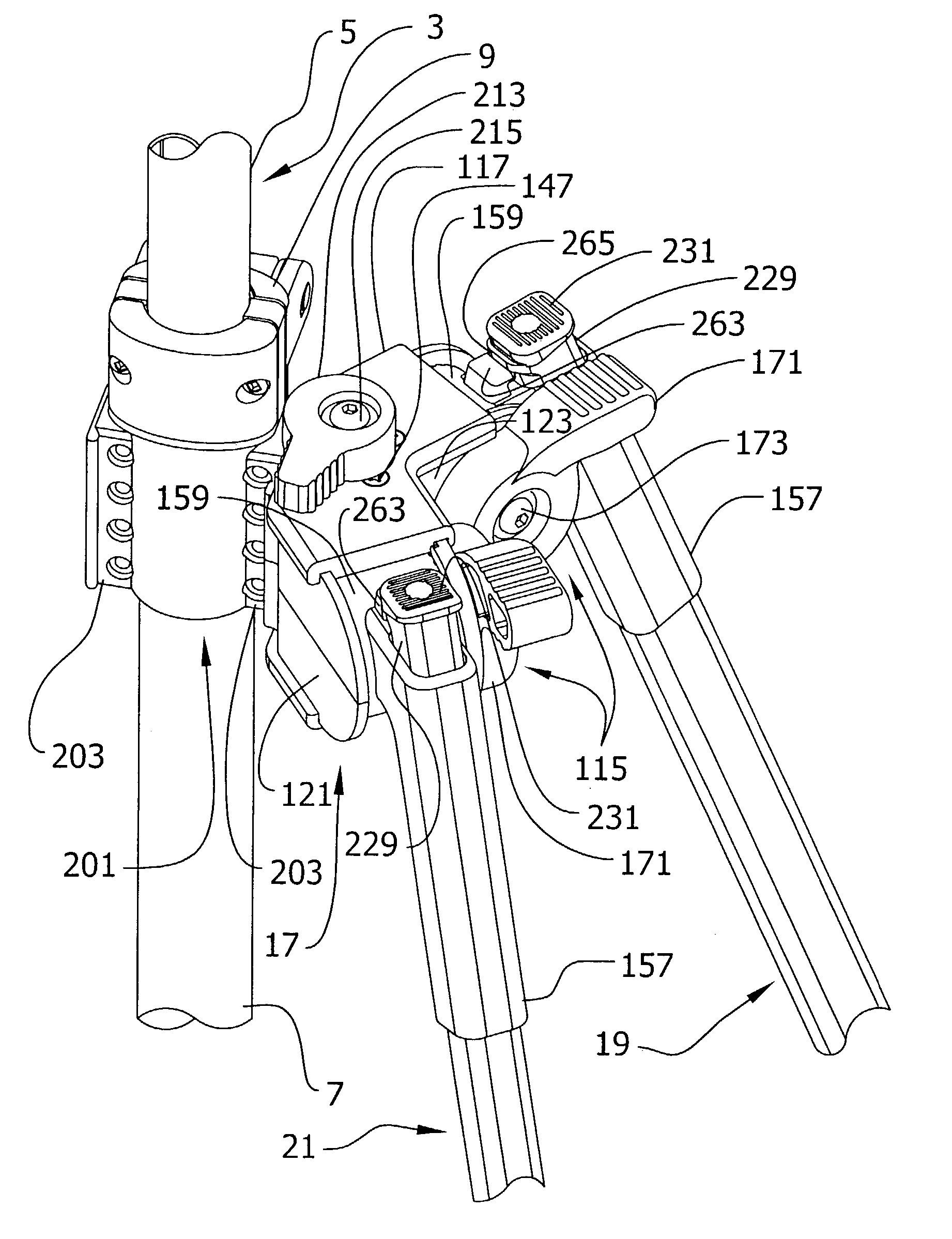
[0118]Mounts 35, 35A, 35B, 201 of the present invention have previously been described in association with the foot (27, 27A, 27B), the joint of the leg sections 23, 25 and in the context of mounting the support(s) to the surveying pole 3. These mounts permit a tongue in groove connection, or a bolted on connection, or both. It to be understood that the mounts do not need to be capable of accepting both bolted and tongue in groove connections. Referring to FIG. 35, a first and modular mounts are shown, including the fixed mount 201 and a selectively positionable mount 267A. The mount 201 located at the upper end of the lower pole section 7 was partially described in regard to attachment of the support 1 to the pole 3. Mount 201 includes a tubular body 269 permanently attached to the surveying pole 3 such as by gluing. The mount 201 is shown separate from the surveying pole 3 in FIG. 36. It may be seen that in addition to the mounting formations 203 and bolt holes 271, the mount 201 ...

second embodiment

[0129]Referring now to FIGS. 55–63, a foot assembly of a second embodiment is designated generally at 356, and shown mounted on the lower end of the second leg section 25. The foot assembly 356 includes a receptacle 360 for receiving a lower end of the second leg section 25 onto a boss 365 at the bottom of the receptacle (FIG. 57) to orient and locate the foot assembly relative to the second leg section. Pan head screws 358 are received through respective openings 359 to secure the foot assembly 356 to the second leg section 25. A foot pad 361 formed as one piece with the receptacle 360 is used to apply foot pressure to drive the foot assembly into the ground. Two generally triangular webs 363 located under the foot pad 361 are arranged perpendicularly to each other in a “T” pattern. The webs 363 strengthen the foot pad 361 and provide stability as will be described.

[0130]The foot pad 361 has a counterbore 362 extending through it which receives a screw 357 used to secure the foot a...


PUM


Abstract

A support capable of supporting geomatic equipment has hinged legs which allow the legs to pivot about a horizontal axis to selected positions. A hinge lock associated with each of the legs allows the leg to be locked in the selected angular position. Locking of the legs in this manner facilitates stability of the support. The locks are readily engaged and disengaged and can be used to hold the legs in a stowed position.

Description

CROSS REFERENCE TO RELATED APPLICATIONS[0001]This application claims the benefit of U.S. Provisional Application 60 / 373,885, filed Apr. 19, 2002, and U.S. Provisional Application 60 / 432,375, filed Dec. 11, 2002.BACKGROUND OF THE INVENTION[0002]This invention relates generally to devices which support and hold equipment and more particularly to a foot for such devices suitable for holding geomatic equipment and accessories.[0003]Although the art of surveying is old, recent improvements in equipment, such as automatic electronic total surveying stations, have increased the accuracy of the surveying instruments far beyond what was possible previously. Where accepted accuracy for equipment in the not too distant past was 20 seconds of a degree, accuracy is now commonly required to be 1 second of a degree. At these levels of precision, the instruments and many of their accessories must be supported in a manner which is consistent and stable. Accordingly, there is a need for closer examin...

Claims


Application Information

Patent Timeline
IPC IPC(8): F16M11/38F16B7/14F16M11/16F16M11/32F16M11/36F16M13/02G01C15/06
CPCF16B7/1463F16M11/16F16M11/32F16M11/36G01C15/06F16M11/10F16M11/28F16M13/02F16M2200/027F16M2200/022
Inventor CRAIN, STEPHEN B.MOORE, CHRISTOPHER T.MIZE, RALPH C.WILLIAMSON, JERRY L.ESSEX, LARRY W.
Owner SECO MFG CO INC
Features
  • R&D
  • Intellectual Property
  • Life Sciences
  • Materials
  • Tech Scout
  • Unparalleled Data Quality
  • Higher Quality Content
  • 60% Fewer Hallucinations
Learn More