Gas bag module

a technology of gas bag and bag body, which is applied in the directions of transportation and packaging, pedestrian/occupant safety arrangements, vehicle safety arrangements, etc., can solve the problems of increasing the number of components and the time required for installation, and achieves the effect of high force take-up and minimal expenditur

Inactive Publication Date: 2006-05-23
TRW AUTOMOTIVE SAFETY SYST
View PDF18 Cites 24 Cited by
  • Summary
  • Abstract
  • Description
  • Claims
  • Application Information

AI Technical Summary

Benefits of technology

[0015]In a preferred embodiment of the invention, the first fastening elements are constructed in the form of straps and the second fastening elements are constructed in the form of hooks. This form of fastening elements can be produced with minimal expenditure, e.g. by an injection-molding process, and offers a secure fastening which makes possible an easy movement of the fastening elements with respect to each other in the insertion direction and, at the same time, permits a high take-up of force perpendicular to the insertion direction by the fastening elements.
[0016]On the covering cap and on the module housing, in addition to the first and second fastening elements, securing latching elements can be provided by means of which, when the first and second fastening elements are in engagement with each other, an additional securing latching connection is formed through which the covering cap is secured on the module housing. Hereby, an unintentional detachment of the covering cap from the module housing, e.g. by shaking loose due to vehicle vibrations, can be prevented.

Problems solved by technology

In order to secure the latching connection, however, generally additional securing elements are necessary which can withstand the high forces occurring; this increases the number of components and also the time required for installation.

Method used


Image

  • Gas bag module
  • Gas bag module
  • Gas bag module

Examples


Embodiment Construction

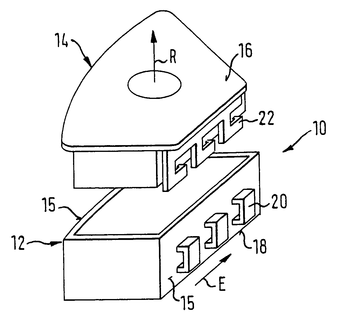
[0024]The gas bag module 10 according to a first embodiment, shown in FIG. 1, has a module housing 12 and a covering cap 14 separate therefrom.

[0025]Both the covering cap 14 and also the module housing 12 in the examples shown here consist of a suitable plastic material, but other materials may also be provided.

[0026]The module housing 12 shown here is a self-contained component. However, it could also be a part of a steering wheel or another part of a vehicle body, on which the covering for a gas bag or a gas bag module is arranged. A gas bag, not shown here, is accommodated in the module housing 12.

[0027]The gas bag module 10 has a module front side 16 and a module rear side 18, which lie substantially opposite each other. The front side 16 of the gas bag module 10 is defined by an outer wall of the covering cap 14 and the module rear side 18 is defined by an outer side of the module housing 12. The direction running from the module rear side 18 to the module front side 16 represe...


PUM


Abstract

A gas bag module comprises a module housing (12) and a covering cap (14), a side wall (15) being provided on at least one of the module housing (12) and the covering cap (14). An outer wall (16) of the covering cap defines a front side of the module and an outer wall (18) of the module housing (12) defines a rear side of the module, whereby an outlet direction (R) is given that runs from the rear side to the front side of the module. The module housing (12) has first fastening elements (20) and the covering cap (14) has second fastening elements (22) which can be brought into engagement with the first fastening elements. The first and second fastening elements (20, 22) are arranged and aligned with respect to the side wall (15) such that the engagement of the first and second fastening elements (20, 22), which prevents an uncoupling of the covering cap (14) and of the module housing (12) in a gas bag outlet direction (R), comes about through a movement of the fastening elements (20, 22) relative to each other in a direction (E) that runs along the side wall (15) and transversely to the outlet direction (R).

Description

TECHNICAL FIELD[0001]The invention relates to a gas bag module comprising a module housing and a covering cap.BACKGROUND OF THE INVENTION[0002]Conventional gas bag modules have a side wall provided on the module housing and / or on the covering cap; an outer wall of the covering cap defines a front face of the module and an outer wall of the module housing defines a rear face of the module, whereby an outlet direction is given that runs from the rear face to the front face of the module. The module housing has first fastening elements and the covering cap has second fastening elements which can be brought into engagement with the first fastening elements.[0003]U.S. Pat. No. 5,409,256 shows a gas bag module in which a covering cap receives a gas bag and has downwardly projecting insert tabs which snap into place in openings of an annular carrier plate of the gas bag module. Assembling the covering cap and the carrier plate takes place with a relative movement between these two parts in...

Claims


Application Information

Patent Timeline
Patent Type & Authority Patents(United States)
IPC IPC(8): B60R21/20B60R21/217
CPCB60R21/217
Inventor SCHNEIDER, MICHAEL
Owner TRW AUTOMOTIVE SAFETY SYST
Why Eureka
Try Eureka