Fluid lubricated bearing device

a technology of lubricating bearings and fluids, which is applied in the direction of sliding contact bearings, instruments, record information storage, etc., can solve the problems of aforementioned lubricating oil leakage, small amount of air inside the housing, and leakage of lubricating oil, so as to improve the rotational accuracy of the bearing and increase the rigidity of the bearing

Inactive Publication Date: 2006-05-23
NTN CORP
View PDF2 Cites 24 Cited by
  • Summary
  • Abstract
  • Description
  • Claims
  • Application Information

AI Technical Summary

Benefits of technology

[0025](2) For changes in pressure from the atmospheric pressure to 0.3 atm at a constant temperature:V90 / V−40=1 / 0.3=3.33 timesAs can be seen from the foregoing, to suppress lubricating oil leakage due to expansion of air, it is desirable to design the fluid lubricated bearing device in consideration of changes in barometric pressure, having a greater effect than temperature, under the environments specified within the range mentioned above in order to configure the device so as to be free from lubricating oil leakage.
[0046]The axial member is provided with a flange portion facing to one end face of the bearing member to generate a hydrodynamic pressure in the thrust bearing gap formed between the end face of the bearing member and the end face of the flange portion, thereby making it also possible to provide non-contact support to the axial member in the direction of thrust. In this case, a larger amount of the lubricating fluid in the thrust bearing gap flows into the grooves due to the effects of centrifugal force. However, the three or more circulation grooves can positively accommodate such a lubricating fluid.

Problems solved by technology

However, depending on the degree of vacuum in the vacuum chamber, there remains a small amount of air inside the housing after having been exposed to the atmospheric pressure.
With a large amount of air remaining in the housing, expansion or contraction of the remaining air due to variations in ambient temperature would cause the lubricating oil to be pushed out of the housing, possibly resulting in leakage of the lubricating oil.
In particular, the motor operating at an inverted or horizontal attitude would cause the lubricating oil to flow in the inner space of the housing to stay on the side of the opening portion, thereby resulting in the aforementioned lubricating oil leakage.
Even with a small amount of air remaining in the housing, the remaining air may be expanded under environments of reduced pressures, such as operations at high altitudes or transportation by airfreight, to push the lubricating oil out of the housing, thereby possibly resulting in leakage of the lubricating oil.

Method used


Image

  • Fluid lubricated bearing device
  • Fluid lubricated bearing device
  • Fluid lubricated bearing device

Examples


example

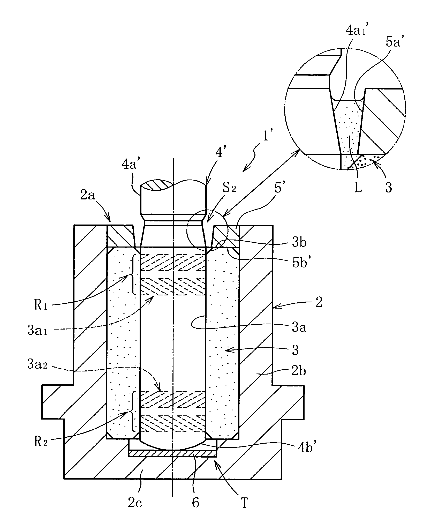
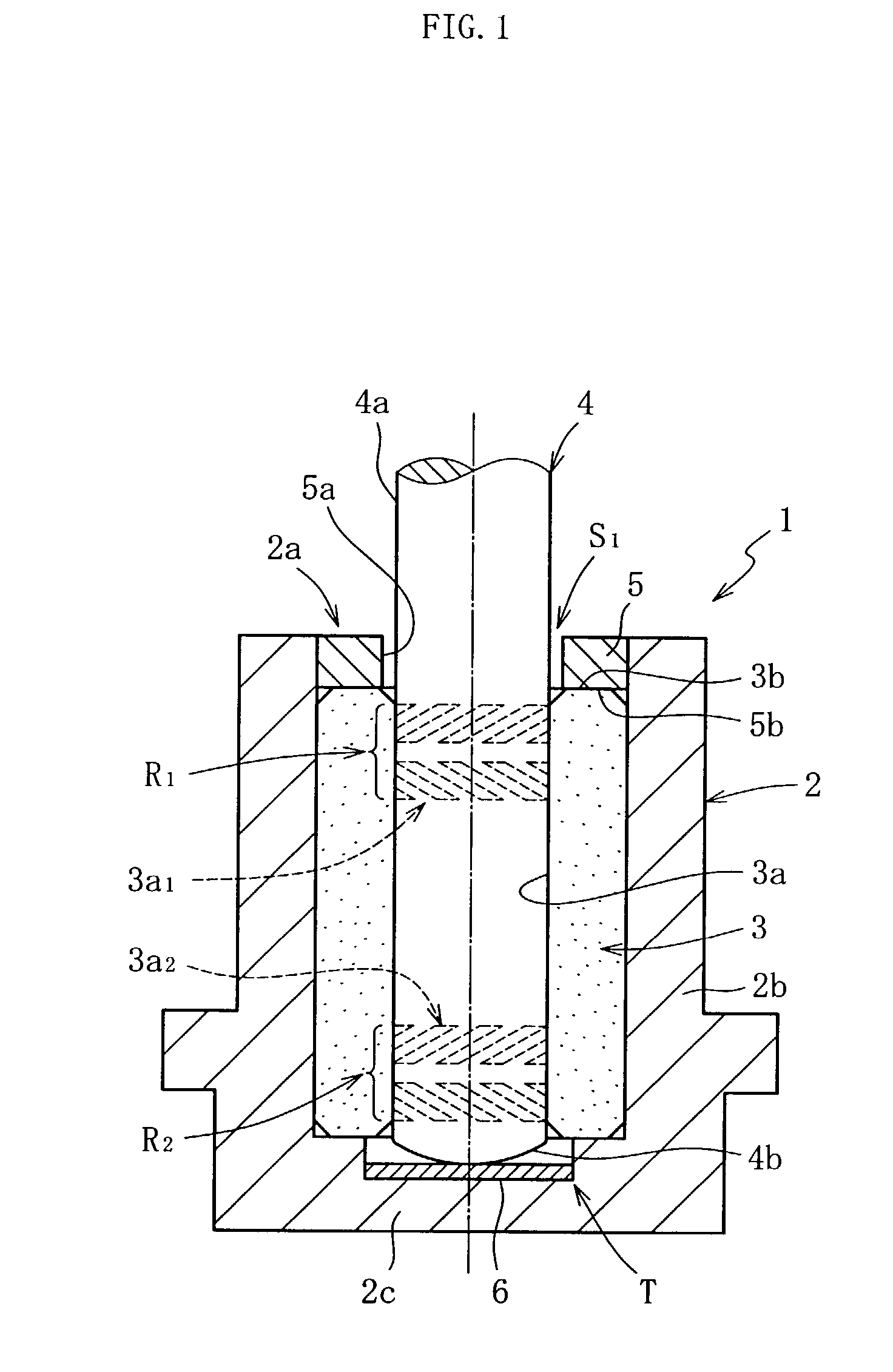
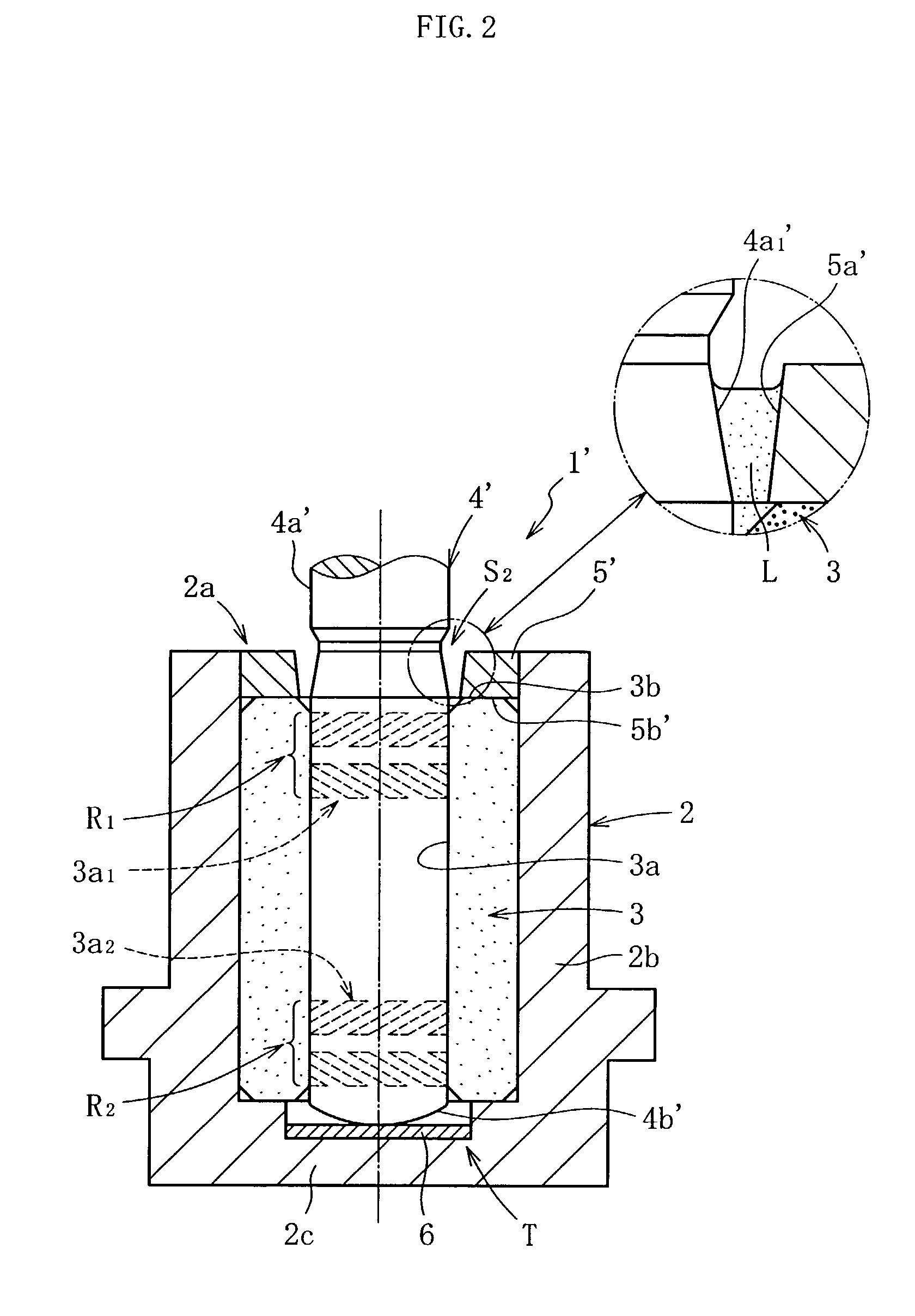
[0112]Bearing devices of five types to be tested (examples 1 to 2 and comparative examples 1 to 3) were fabricated by loading a lubricating oil in the aforementioned manner (by vacuum pressure impregnation) into the fluid lubricated bearing devices 1, configured as shown in FIG. 1, with the vacuum chamber being kept at different levels of vacuum to thereby have different amounts of air remaining in the inner space of the housing 2 after exposed to the atmospheric pressure. It is difficult to measure the amount of air remaining in the inner space of the housing after the lubricating oil has been loaded therein by vacuum pressure impregnation. However, for example, it can be estimated that air of 50 vol % of the inner space volume remains inside the housing after exposed to the atmospheric pressure when the vacuum chamber is reduced in pressure to 380 Torr (half the atmospheric pressure). This approach was used to estimate the amount of air remaining in the housing inner space.

[0113]E...


PUM

PropertyMeasurementUnit
pressureaaaaaaaaaa
Storage temperatureaaaaaaaaaa
Operating temperatureaaaaaaaaaa

Abstract

An inner space of a housing sealed with a seal member as well as internal pores of a bearing member (pores in a porous structure) are filled with a lubricating oil without the presence of air, so that the oil surface of the lubricating oil is within a seal space. Under a reduced pressure of 100 Torr, no lubricating oil leaks outside of the housing even at any attitude of the fluid lubricated bearing device such as normal, inverted, or horizontal attitude.

Description

CROSS-REFERENCE TO RELATED APPLICATION[0001]This application claims the priority benefit of Japan applications serial no. 2001-347725, filed Nov. 13, 2001, 2002-29520, filed Feb. 6, 2002, 2002-35790, filed Feb. 13, 2002 and 2002-281599, filed Sep. 26, 2002.BACKGROUND OF THE INVENTION[0002]1. Field of the Invention[0003]The present invention relates to a fluid lubricated bearing device for allowing a lubricating oil film to be produced in a radial bearing gap to provide non-contact support of a rotating member. For example, this bearing device is suitable for use with: spindle motors incorporated into information apparatus, for example, a magnetic disk device such as an HDD or FDD, an optical disk device such as a CD-ROM, CD-R / RW, or DVD-ROM, a magneto-optical disk device such as an MD or MO; scanner motors incorporated into a copier, laser beam printer (LBP), or barcode reader; and small motors incorporated into electric appliances such as an axial fan.[0004]2. Description of the Re...

Claims


Application Information

Patent Timeline
Patent Type & Authority Patents(United States)
IPC IPC(8): F16C17/10F16C33/10F16C33/74G11B19/20
CPCF16C17/026F16C17/107F16C33/103F16C33/107F16C41/008G11B19/2009F16C33/745F16C33/1075F16C2370/12F16C17/028
Inventor KURIMURA, TETSUYAYAMAMOTO, YASUHIROKAWASE, TATSUO
Owner NTN CORP
Why Eureka
Try Eureka