High moment of inertia putter

a putter and high moment technology, applied in the field of golf putters, to achieve the effect of light weight and inexpensive manufacturing

Inactive Publication Date: 2006-05-23
MACGREGOR GOLF
View PDF42 Cites 50 Cited by
  • Summary
  • Abstract
  • Description
  • Claims
  • Application Information

AI Technical Summary

Benefits of technology

[0013]The trailing wall is spaced in trailing relation to the leading wall by a sufficient distance to position a center of gravity of the putter head about two-thirds of the way between the leading wall and the trailing wall. Accordingly, the center of gravity is closer to the trailing wall than to the leading wall. Such positioning of the center of gravity provides an enhanced moment of inertia to minimize the effects of a putt that misses a sweet spot on a ball-striking surface that is adapted to be mounted to the leading wall.
[0015]A weight means is positioned within the cavity to further enhance the moment of inertia by positioning the center of gravity further away from the leading wall and closer to the trailing wall.
[0018]An important object of this invention is to provide a golf putter head having a moment of inertia greater than 4,000 gm cm2. A closely related object is to accomplish the foregoing object in a putter head that is light-in-weight and inexpensive to manufacture.
[0019]Another important object is to provide a high moment of inertia putter head having an acceptable, aesthetically-pleasing size.

Problems solved by technology

However, when the sweet spot is missed, the inertia offered by the ball imparts a torque to the golf club shaft.

Method used


Image

  • High moment of inertia putter
  • High moment of inertia putter
  • High moment of inertia putter

Examples


second embodiment

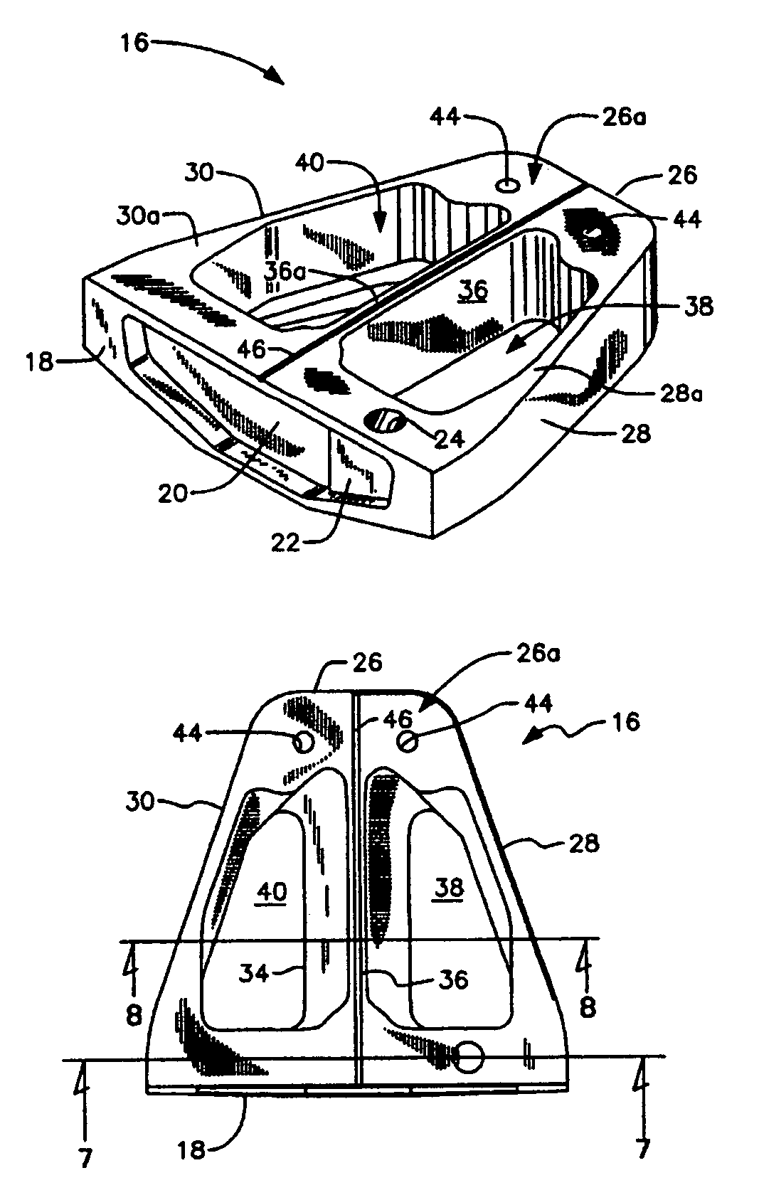
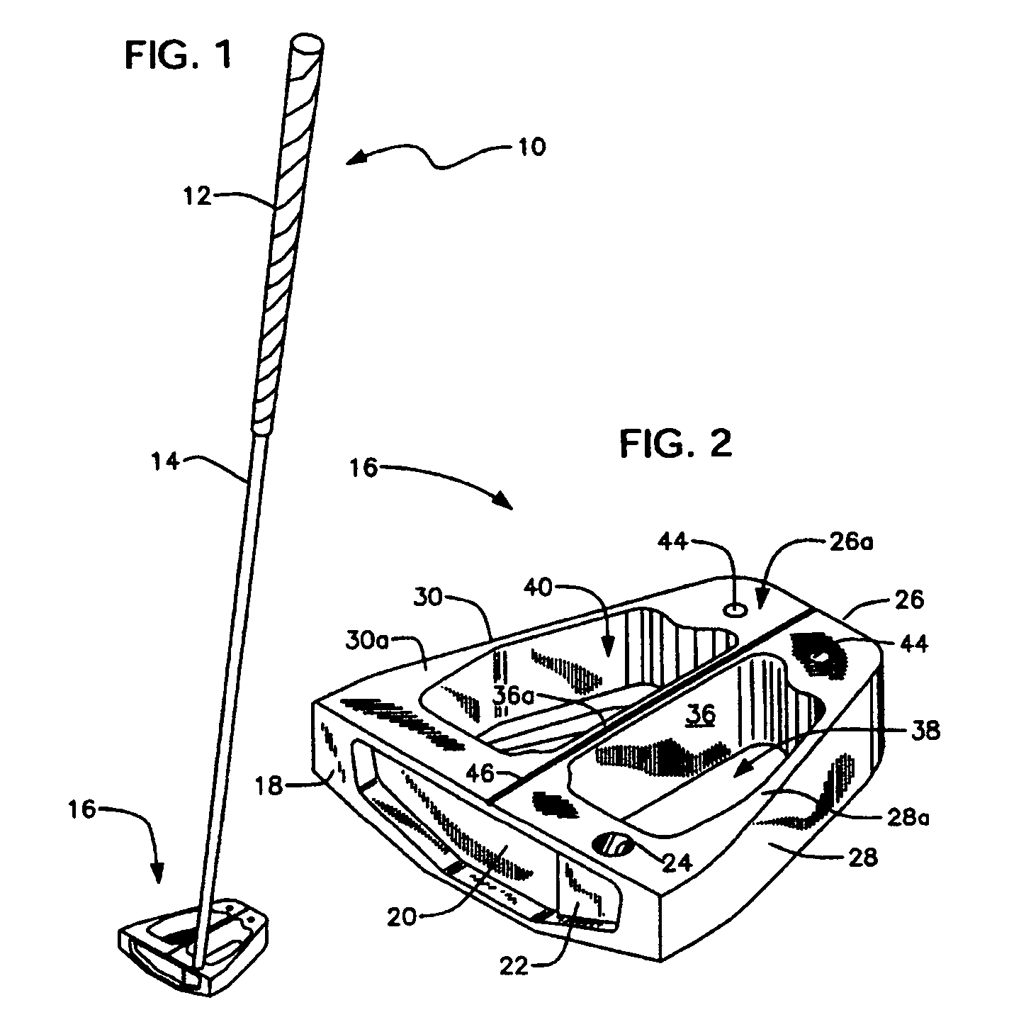
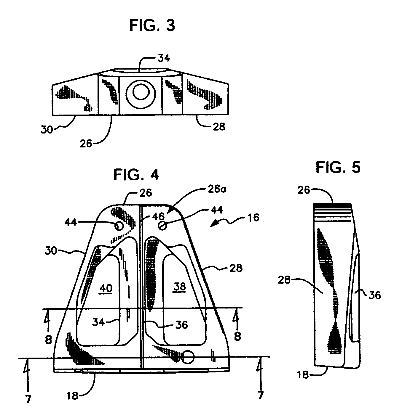
[0044]The center of gravity is moved further from leading wall 18, and the moment of inertia thereby increased, by adding a weight means to trailing end 26a. A weighted putter head represents this invention. Such a weight means is denoted 42 in FIG. 6. Cavity 42a is milled into trailing end 26a to accommodate said weight means, and said weight means is flush with the top of cavity 42a when the weight means is secured therewithin by suitable fastening means such as fasteners 44, 44 (FIGS. 2 and 4).

[0045]Where weight means 42 is formed of copper, the moment of inertia of putter head 16 is approximately 5860 gm cm2. Where weight means 42 is formed of a 25 / 75 copper / tungsten mixture, the moment of inertia is about 6800 gm cm2, and where weight means 42 is formed of tungsten only, the moment of inertia is about 7200.

[0046]Where weight means 42 is formed of copper, the center of gravity of putter head 16 is positioned about 60% of the distance from leading wall 18 to trailing wall 26. Whe...

third embodiment

[0047]In a third embodiment, depicted in FIGS. 9 and 10, web 36 is obviated and a single cavity 39 is thereby provided. Thus, groove 46 is broken up into truncate leading part 46a and truncate trailing part 46b, but said truncate parts still collectively provide a sighting line that a golfer can use when lining up a putt.

[0048]The elimination of web 36 moves the center of gravity still further to the trailing side of leading wall 18, relative to the first two embodiments, and the moment of inertia may therefore be increased further still, depending upon whether a weight means is added to trailing part 26a as in the second embodiment hereof.

[0049]FIG. 10 also indicates that strengthening insert 22a is moved to an opposite end of recess 20 for a left-handed golfer, and that blind bore 24 is re-positioned as well.

[0050]The high moments of inertia of achieved by these embodiments of the inventive putter head have never before been achieved in a golf putter having a leading wall that is ...


PUM


Abstract

A golf putter head has a generally triangular shape where a ball-striking leading wall has a first breadth greater than a second breadth of a trailing wall. The leading wall and trailing wall are interconnected at their respective opposite ends by sidewalls that converge toward one another and define a cavity having a trapezoidal shape. The center of gravity of the golf putter head is closer to the trailing wall than the leading wall so that a moment of inertia is generated that reduces the effects of missing a sweet spot on the leading wall during a putt. In a second embodiment, the trailing wall is weighted to move the center of gravity still closer to the trailing wall. In a third embodiment, a web interconnects the leading and trailing walls along a longitudinal axis of the golf putter head, dividing the cavity into two equal-sized cavities.

Description

[0001]This application is a continuation application of application Ser. No. 10 / 248,342, filed Jan. 10, 2003, the entire content of which is hereby incorporated by reference.BACKGROUND OF INVENTION[0002]1. Field of the Invention[0003]This invention relates, generally, to golf putters. More particularly, it relates to a golf putter of generally triangular configuration having a high moment of inertia.[0004]2. Description of the Prior Art[0005]In a perfect putt, the golfer strikes the ball exactly on the sweet spot of the putter head. This prevents the putter head from twisting about the axis defined by the golf club shaft. However, when the sweet spot is missed, the inertia offered by the ball imparts a torque to the golf club shaft. The torque increases in direct proportion to the distance by which the sweet spot is missed.[0006]A putter head having a high moment of inertia resists the torque caused by missing the sweet spot. Putter heads having high moments of inertia are typically...

Claims


Application Information

Patent Timeline
Patent Type & Authority Patents(United States)
IPC IPC(8): A63B69/36A63B53/04A63B53/06
CPCA63B53/0487A63B59/0088A63B2053/0441A63B2053/0416A63B2053/0491A63B60/02A63B60/50A63B53/0416A63B53/0441
Inventor GRACE, ROBERT M.
Owner MACGREGOR GOLF
Why Eureka
Try Eureka