Antenna unit and portable wireless device

a portable wireless and antenna unit technology, applied in the direction of wireless communication, collapsible antenna means, protective material radiating elements, etc., can solve the problems of rotating mechanism or portable telephone housing breakage, and achieve the effect of preventing the breakage of the antenna uni

Inactive Publication Date: 2006-05-23
SONY MOBILE COMM INC
View PDF11 Cites 19 Cited by
  • Summary
  • Abstract
  • Description
  • Claims
  • Application Information

AI Technical Summary

Benefits of technology

[0006]In view of the foregoing, an object of this invention is to provide an antenna unit and a portable wireless device which are capable of preventing breakage of the antenna unit and the portable wireless device housing due to an external force applied to the antenna being in an upright position.

Problems solved by technology

The flip-up antennae, however, have a problem in that, if such an excessive external force as to rotate the antennae further is applied to the antennae being in an upright position, the antennae, the rotation mechanism or the portable telephone housings may be broken.

Method used


Image

  • Antenna unit and portable wireless device
  • Antenna unit and portable wireless device
  • Antenna unit and portable wireless device

Examples


Embodiment Construction

[0017]Preferred embodiments of this invention will be described with reference to the accompanying drawings:

(1) Entire Construction of Portable Telephone

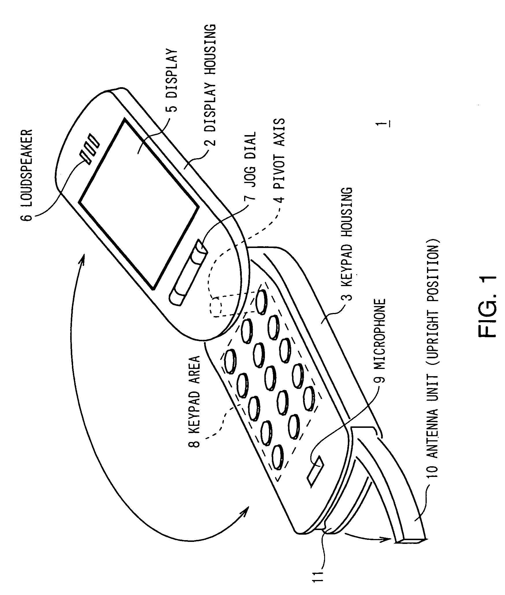
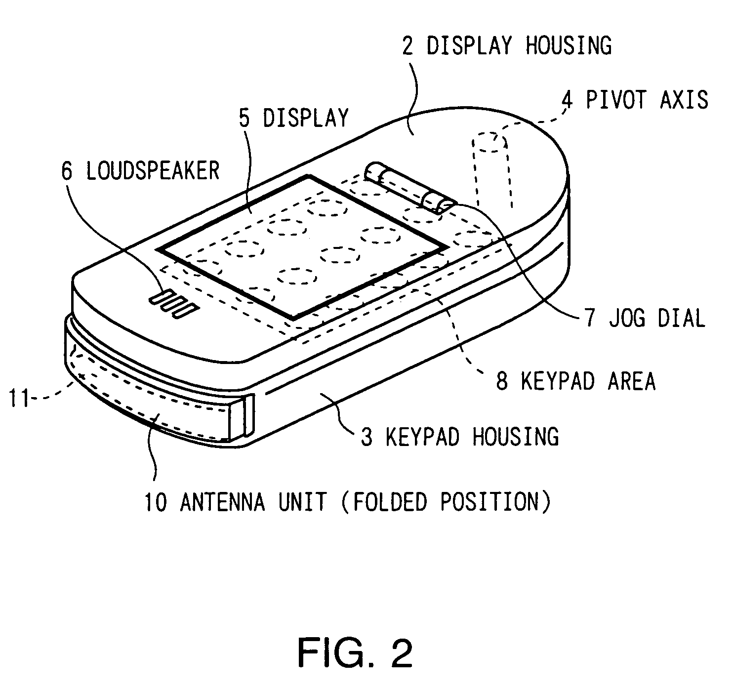
[0018]Referring to FIG. 1, reference numeral 1 shows a portable telephone as a portable wireless device to which this invention is applied. A display housing 2 and a keypad housing 3 are rotatably connected to each other via a pivot axis 4 mounted on one end of the keypad housing 3, so that the housings 2 and 3 are rotatable between an open state shown in FIG. 1 and a closed state shown in FIG. 2 where the housing 2 sits on the top of the housing 3.

[0019]Arranged on the front surface of the display housing 2 are a display 5 comprising a liquid crystal display in its center, a loudspeaker 6 above the display 5, and a jog dial 7 which can be rotated and pressed, below the display 5. On the other hand, arranged on the keypad housing 3 are a keypad area 8 composed of a plurality of buttons in its center and a microphone 9 below the keyp...


PUM


Abstract

In a rotatable antenna unit capable of being externally rotated away from and folded in a portable wireless device, an antenna detachment mechanism is provided, the antenna detachment mechanism composed of a bearing for rotatably supporting the antenna unit on the device by inserting therein and holding a pivot axis mounted on the device and an opening formed by cutting a part of the bearing. As a result, when an excessive external force is applied to the antenna unit being in an upright position, the opening is widened and the antenna unit comes off the portable wireless device. This prevents the antenna unit from being broken.

Description

BACKGROUND OF THE INVENTION[0001]1. Field of the Invention[0002]This invention relates to an antenna unit and a portable wireless device, and more particularly, is suitably applied to a portable telephone.[0003]2. Description of the Related Art[0004]There are portable telephones that have rotatable (flip-up) antennae which have a rotation mechanism so as to be folded into the telephones for realizing both of improved antenna gain while used and improved portability while unused. (For example, Japanese Patent Laid Open No. 8-298406).[0005]The flip-up antennae, however, have a problem in that, if such an excessive external force as to rotate the antennae further is applied to the antennae being in an upright position, the antennae, the rotation mechanism or the portable telephone housings may be broken.SUMMARY OF THE INVENTION[0006]In view of the foregoing, an object of this invention is to provide an antenna unit and a portable wireless device which are capable of preventing breakage...

Claims


Application Information

Patent Timeline
Patent Type & Authority Patents(United States)
IPC IPC(8): H01Q1/24H04M1/00H01Q1/40H01Q1/08H01Q1/12H04M1/02H04W88/02
CPCH01Q1/244H01Q1/084H01Q1/24
Inventor SAITO, YUICHIROITO, KEN
Owner SONY MOBILE COMM INC
Why Eureka
Try Eureka