Optical scanning device and imaging apparatus implementing the same

a scanning device and optical scanning technology, applied in the field of optical scanning devices and imaging apparatuses, can solve the problems of difficult to realize the above arrangement, the limit of the attempt to increase the recording speed, and the unevenness of the image density

Inactive Publication Date: 2006-05-23
RICOH KK
View PDF11 Cites 67 Cited by
  • Summary
  • Abstract
  • Description
  • Claims
  • Application Information

AI Technical Summary

Benefits of technology

[0024]The present invention has been developed in response to the above described problems of the related art, and its object is to provide an optical scanning device that implements a resin lens having a power that is an inverse power of the scanning lens in an optical system placed before a deflector so that a change in the beam pitch due to environmental temperature change can be controlled even when a resin lens is used as a scanning lens.
[0025]Also, it is an object of the present invention to realize a reduction of costs and power consumption in an optical scanning device that converts a bundle of rays passing through a coupling optical system into diverging rays and lowers magnification in a sub scanning direction compared to the related art in which a displacement of dots in the main scanning direction or a difference in the write width (scanning width) of each beam are prevented, a misplacement of an image formation position is compensated for, and the image formation position is adjusted mechanically.
[0044]the resin imaging element of the second optical system has a negative power in the sub scanning direction and a surface configuration that is arranged to effectively compensate for a change in field curvature caused by a temperature change in at least one of a support member of the first optical system and the resin imaging element in the third optical system.
[0050]Additionally, the resin imaging element of the second optical system may have at least two surfaces that have negative powers in the sub scanning direction, the surfaces being configured to effectively compensate for the change in field curvature caused by a temperature change in at least one of a support member of the first optical system and the resin imaging element of the third optical system.

Problems solved by technology

However, in this method, factors such as the durability of the motor, the noise, the oscillation, and the modulation speed of the semiconductor laser impose limitations on attempts at increasing the recording speed.
Thereby, in a multi-beam scanning optical system using the resin lens, the scanning line spacing for the plurality of scanning lines in the sub-scanning direction (referred to as ‘beam pitch’ hereinafter) is varied, causing image degradation such as unevenness in image density.
However, the above arrangement is difficult to realize since errors during the mounting of the devices and the like cannot be completely eliminated.
As described above, when the bundle of rays that has passed through the coupling optical system is converted into diverging rays, degradation of the image such as unevenness in density or distortion of the vertical lines may occur due to the displacement of dots in the main scanning direction or the difference in the write width (scanning width) of each beam.
When a field curvature is generated as a result of the above change in the curvature radius or the refractive index, the beam spot written on the photoconductor will be enlarged, leading to image degradation.
However, the resin lenses implemented between the light source and the light deflector have no power in the main scanning direction and thus have no compensation capabilities for the change in field curvature in the main scanning direction caused by the temperature change of the resin scanning lens.
The problem with this prior art invention is that the temperature compensating function is provided only on one surface of the lens.
With this arrangement, the flexibility in design will also be restricted.
However, the temperature compensation function is only provided on one surface of the lens.
However, costs will be raised and the power consumption of the device will increase due to the extra parts required for the mechanical structure and a detector that detects the misplacement of the image formation position.
As described above, in the resin lens, the change in the curvature radius or the refractive index due to environmental temperature change is greater compared to a glass lens, and therefore, a field curvature is generated in the optical system that implements the resin lens and the beam spot diameter formed on the photoconductor is enlarged, resulting in image degradation.

Method used


Image

  • Optical scanning device and imaging apparatus implementing the same
  • Optical scanning device and imaging apparatus implementing the same
  • Optical scanning device and imaging apparatus implementing the same

Examples


first embodiment

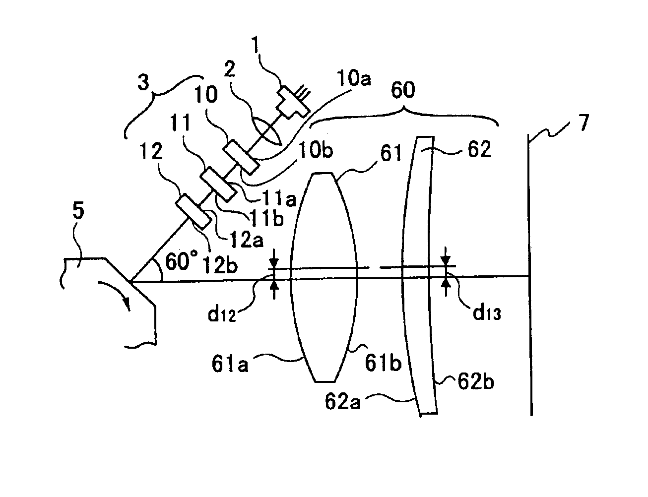
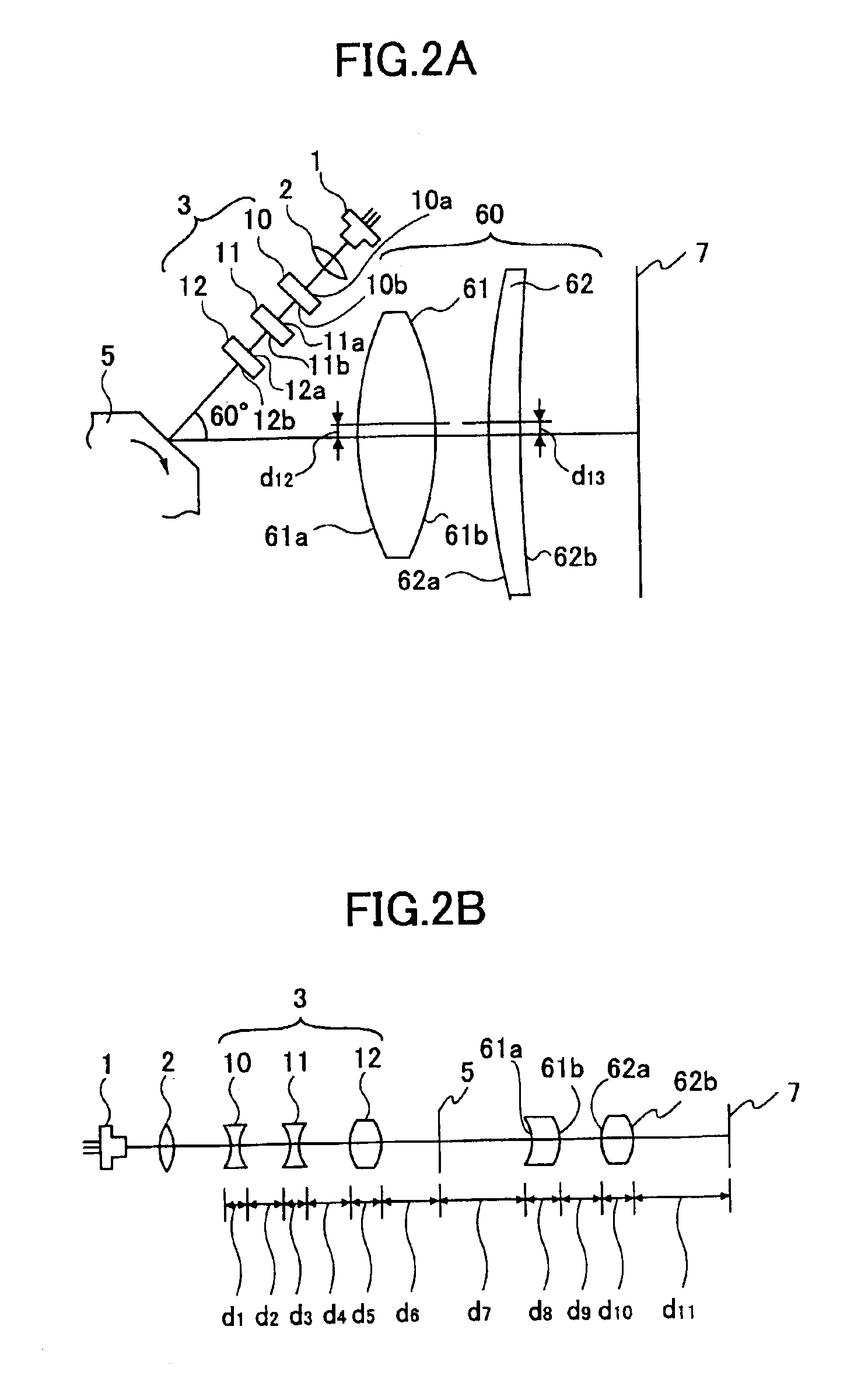
[0069]FIGS. 2A and 2B are diagrams illustrating an optical scanning device according to the present invention, wherein FIG. 2A is a schematic diagram of the optical scanning device, and FIG. 2B is a side view (optical path) diagram of the same optical scanning device. In this embodiment, a plurality of light ray bundles emitted from a light source 1 are coupled into a desired state by means of a coupling lens 2 (first optical system). Herein, the rays are coupled into substantially parallel (or collimated) rays. Also, in this example, a LDA (laser diode array) having a plurality of emission points is used as the light source 1. The light source 1 may also be a plurality of laser diodes that emit multi-beam light synthesized by a prism.

[0070]By using a plurality of light sources as described above, the rotation speed of a light deflector can be lowered, thereby extending the life and reducing the power consumption of the optical scanning device.

[0071]As for the coupling lens 2, a sin...

embodiment 1

[0091](Embodiment 1)

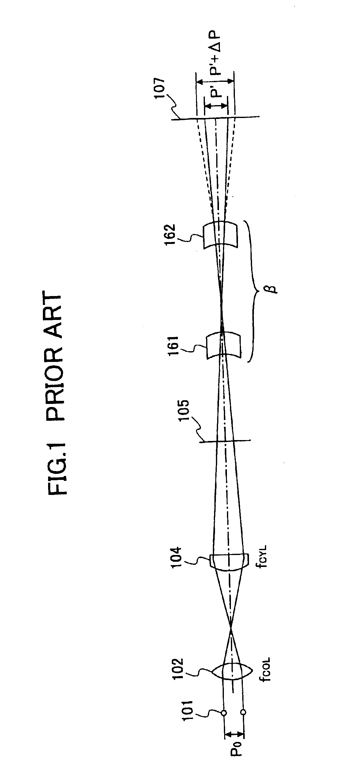
[0092]In the following, the change in the beam pitch in the optical scanning device shown in FIG. 1 obtained from the above formulas describing the surface configurations are given.

[0093]‘Light Source’[0094]14 μm-pitch 4-channel LDA[0095]wavelength: 780 nm[0096]slanting angle: 12.39°

[0097]‘Coupling Lens’[0098]focal length: 27 mm[0099]coupling effect: collimating effect

[0100]‘Polygon Mirror’[0101]number of reflective surfaces: 5[0102]in-circle radius: 18 mm[0103]Angle formed between the incident angle of the beam emitted from the light source and the optical axis of the scanning optical system: 60°[0104]Write width: ±150 mm[0105]Field angle: ±38°[0106]Write density: 1200 dpi[0107]d1=3 mm, d2=9.2 mm, d3=3 mm, d4=8.15 mm, d5=6 mm, d6=114 mm, Curvature radius of the surface of incidence 10a of the resin lens 10: −119.97 mm (spherical);[0108]Curvature radius of the exit surface 10b of the resin lens 10: ∞ (main scanning) and 16.4 mm (sub scanning);[0109]Curvature radi...

embodiment 2

[0158](Embodiment 2)

[0159]In the following, the change in the beam spot diameter in the optical scanning device shown in FIGS. 5A and 5B obtained from the above formulas describing the surface configurations are given.

[0160]‘Light Source’[0161]14 μm-pitch 4-channel LDA[0162]wavelength: 780 nm[0163]inclination angle: 50.68°

[0164]‘Coupling Lens’[0165]focal length: 27 mm[0166]coupling effect: diverging effect

[0167]‘Polygon Mirror’[0168]number of reflective surfaces: 5[0169]in-circle radius: 18 mm[0170]Angle formed between the incident angle of the beam emitted from the light source and the optical axis of the scanning optical system: 60°[0171]Write width: ±150 mm[0172]Field angle: ±38°[0173]Write density: 1200 dpi[0174]L1=8 mm, L2=39.4 mm, d1=3 mm, d2=20.35 mm, d3=6 mm, d4=138.5 mm,[0175]Curvature radius of the surface of incidence 13a of the resin lens 13: −135.34 mm (main scanning) and −30 mm (sub scanning);[0176]Curvature radius of the exit surface 13b of the resin lens 13: ∞ (main ...


PUM


Abstract

An optical scanning device, including a resin lens having a power that is an inverse power of scanning lens placed before a deflector. A bundle of rays emitted from a plurality of light sources is coupled into a desired state by coupling lens, after which the bundle of rays is incident on the resin lens. The surface of incidence of the resin lens has a spherical surface with a negative power, and the exit surface of this resin lens has a cylindircal surface with a negative power only in the sub scanning direction. The bundle of rays passes through the resin lens and enters a glass toroidal lens. A light deflector deflects the bundle of rays from the toroidal lens. The deflected bundle of rays is incident on a third optical system that condenses the deflected bundle of rays onto a surface to be scanned.

Description

BACKGROUND OF THE INVENTION[0001]1. Field of the Invention[0002]The present invention relates generally to an optical scanning device and an imaging apparatus implementing this optical scanning device, and particularly to a multi-beam optical scanning device that simultaneously scans a surface to be scanned such as a photoconductor using a plurality of light beams so as to significantly increase recording speed, this multi-beam optical scanning device being suitable for use in a write system of a recording device such as a digital copier, a laser printer, or a laser facsimile.[0003]2. Description of the Related Art[0004]One known method of increasing the recording speed of an optical scanning device implemented in a write system of a recording device such as a laser printer or a laser facsimile is a method of increasing the rotation speed of a polygon mirror, which functions as a deflector. However, in this method, factors such as the durability of the motor, the noise, the oscillat...

Claims


Application Information

Patent Timeline
Patent Type & Authority Patents(United States)
IPC IPC(8): G02B26/08B41J2/44G02B13/00G02B13/18G02B26/10G02B26/12H04N1/036H04N1/113
CPCG02B26/123
Inventor ATSUUMI, HIROMICHIHAYASHI, YOSHINORIMIYATAKE, NAOKI
Owner RICOH KK
Why Eureka
Try Eureka