Method and apparatus for controlling damping of a vehicle suspension

a technology of suspension and damper, applied in the field of active control of vehicle suspension systems, can solve the problems of damper system control valve noise and often unattainable control force, and achieve the effects of reducing noise, vibration and harshness, and limiting the rate of damper setting chang

Active Publication Date: 2007-10-23
GM GLOBAL TECH OPERATIONS LLC
View PDF20 Cites 40 Cited by
  • Summary
  • Abstract
  • Description
  • Claims
  • Application Information

AI Technical Summary

Benefits of technology

[0005]The invention includes a control algorithm for semi-active suspension dampers. The concept is to provide low-cost, effective suspension system having a limited number of sensors. A typical prior art suspension control algorithm needs special functions to address potential harshness problems. In this invention, the control signal output to each damper is damper setting, rather than force. The result is significantly less high frequency content in damper control, and an ability to prevent damper control to a hard setting at a near-zero damper velocity. All dampers are preferably controlled simultaneously. When applied to a vehicle, there is a balanced damper setting front-to-rear, through the use of calibration lookup tables.
[0006]The invention measures up to three degrees of freedom off motion on the vehicle body to calculate modal velocities. The dampers are continuously adjusted in phase depending on the measured modal velocities. Other existing signals used as inputs include vehicle speed, steering wheel angle, applied brake pressure, and vehicle lateral acceleration. The control output is damper setting. This changes the dominating frequency of the current control from 15 Hz to a range of 2-3 Hz, thus reducing the risk for control valve noise.
[0007]The algorithm reduces the need for sensors, e.g. accelerometers, and provides the benefits of semi-active dampers. The main control inputs are vehicle reference speed and body modal velocities. The output from the body modal control is a control request, comprising a signal which is a percentage of the damper control range. The output comprises a single signal or channel, and each signal is translated to a front and rear setting, using a translation table. There is no requirement for information about wheel or damper movement, in contrast to prior art systems. However if, for example, height sensors are implemented in the vehicle for use in another subsystem, the information can be used to provide additional information for the damper control.
[0015]Another aspect of the invention includes limiting a rate of change of the damper setting.
[0016]The benefits of the system, in the form of effect upon cost, durability, and system performance include a cost reduction resulting from use of fewer sensors than current systems. Furthermore, magnitude of noise, vibration and harshness (NVH) are reduced due to less valve noise. The system, having fewer components, e.g. sensors, is less likely to experience faults, leading to improved system reliability. The system is simpler to tune due to less need for special functions.

Problems solved by technology

Another area of concern for current systems which provide damping by controlling damping force is that when force requests are not correlated to damper velocities, the control force is often unattainable.
This last effect leads to problems with damping system control valve noise.

Method used


Image

  • Method and apparatus for controlling damping of a vehicle suspension
  • Method and apparatus for controlling damping of a vehicle suspension
  • Method and apparatus for controlling damping of a vehicle suspension

Examples


Embodiment Construction

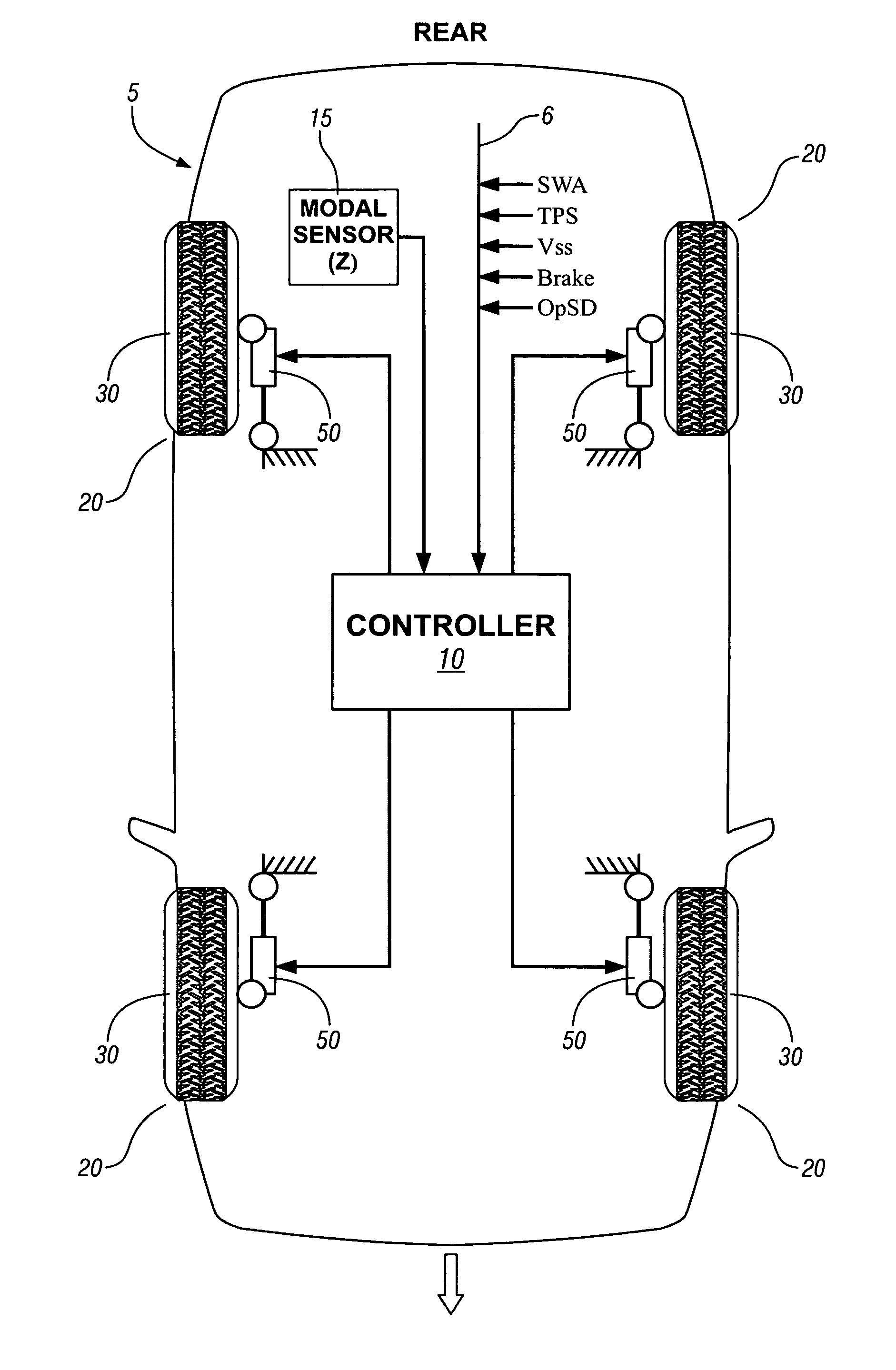
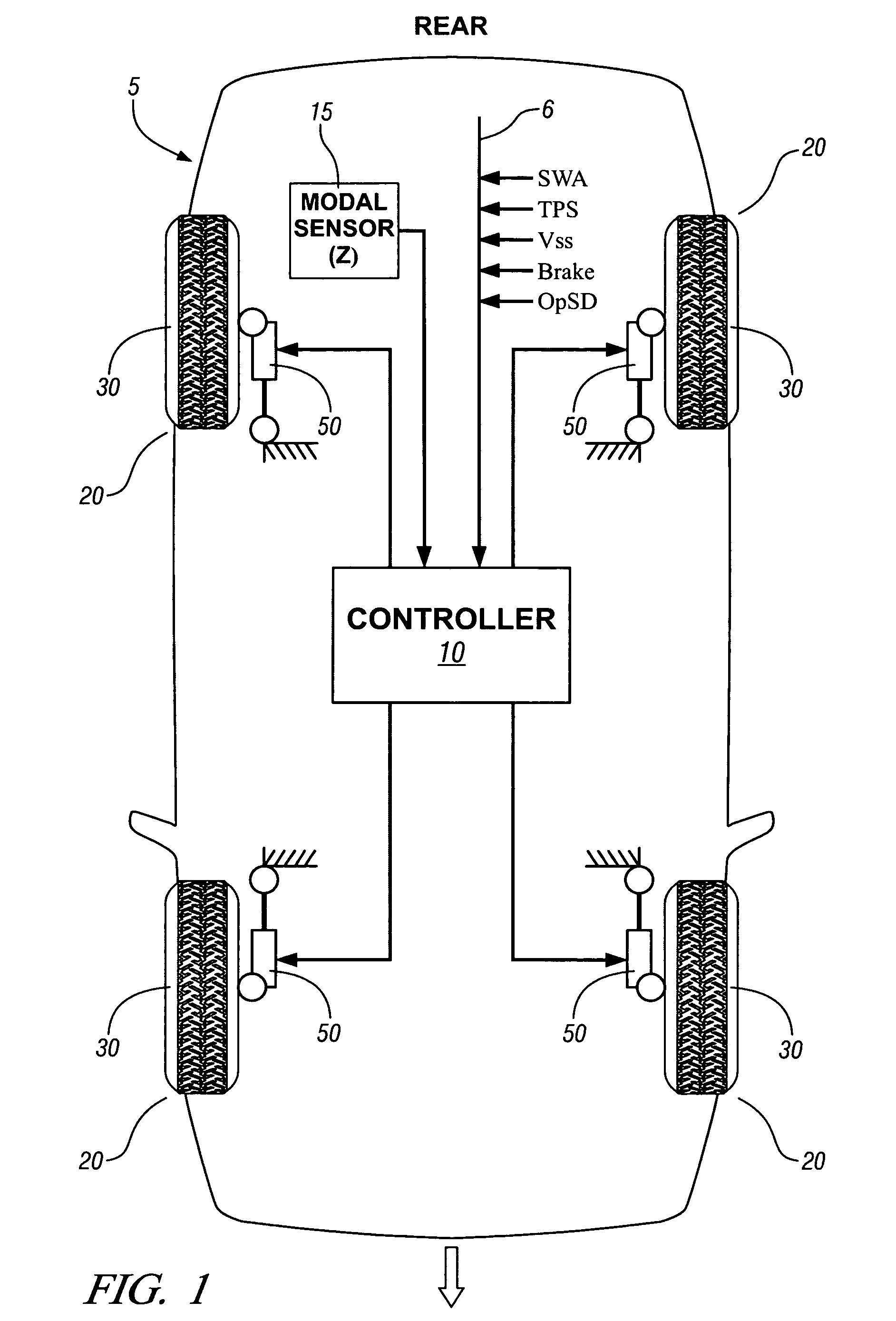
[0021]Referring now to the drawings, wherein the showings are for the purpose of illustrating the invention only and not for the purpose of limiting the same, FIG. 1 shows a system which has been constructed in accordance with an embodiment of the present invention. The exemplary system comprises a passenger vehicle 5 intended for use on highways, although it is understood that the invention described herein is applicable on vehicles and other suspended bodies that are able to employ a controllable suspension damping system.

[0022]Referring again to FIG. 1, the exemplary vehicle 5 includes a plurality of systems, including a propulsion system and a controllable suspension damping system. The vehicle architecture preferably includes a control system operable to control various vehicle systems through execution of embedded algorithms and calibrations. The typical control system is able to control various vehicle systems by using one or more embedded controllers to execute on-board algo...


PUM


Abstract

A method and algorithm for semi-active suspension damper control is described. The algorithm controls the damper setting to limit vehicle body movement in terms of body modal velocities of heave, roll and pitch. The main input, body movement, is measured with accelerometers. The control output comprises a request in percent of damper control range. Vehicle speed-dependent minimum and maximum limits are applied. The method includes monitoring vehicle speed and a modal sensing system. A common damping rate for the dampers is determined based upon parameters for speed, heave, pitch, and roll. Each damper is controlled based upon the common damping rate adjusted based upon a location of each of the controllable suspension dampers. The output comprises a single signal, translated to a front and rear setting. The purpose is to always have a balanced setting of the four dampers.

Description

CROSS-REFERENCE TO RELATED APPLICATIONS[0001]This application claims priority from U.S. Provisional Application No. 60 / 727,599, filed Oct. 17, 2005, entitled METHOD AND APPARATUS FOR CONTROLLING DAMPING OF A VEHICLE SUSPENSION. TECHNICAL FIELD[0002]This invention pertains generally to vehicle systems, and more specifically to active control of vehicle suspension systems.BACKGROUND OF THE INVENTION[0003]Current systems for controlling active vehicle suspensions require many sensors, including, e.g. accelerometers. A typical system includes a standard sensor layout requiring as many as five accelerometers, including three on the car body to measure heave, pitch and roll, and one at each of the front wheels. Another area of concern for current systems which provide damping by controlling damping force is that when force requests are not correlated to damper velocities, the control force is often unattainable. The result may be that a requested damping force is only realized on one or s...

Claims


Application Information

Patent Timeline
Patent Type & Authority Patents(United States)
IPC IPC(8): B60G17/00
CPCB60G17/018B60G17/08B60G2500/106B60G2400/0512B60G2400/204B60G2400/0511
Inventor NORDGREN, JOHNWAHLBERG, ROBERTOSTLUND, TOMAS
Owner GM GLOBAL TECH OPERATIONS LLC
Why Eureka
Try Eureka