Charge Pump

Inactive Publication Date: 2008-11-06
TEXAS INSTR INC
View PDF8 Cites 33 Cited by
  • Summary
  • Abstract
  • Description
  • Claims
  • Application Information

AI Technical Summary

Benefits of technology

[0010]If the time constant of the control loop is substantially greater than a period of the switching sequence of the switching means, the current drawn from the current source is substantially constant. Charging and discharging the flying capacitor using a constant current means that the current drawn by the charge pump is constant. This reduces voltage ripples in the power supply.
[0011]The charge pump preferably comprises a controller controlling the switching means. The switching means preferably comprises a first switching path for switching current through

Problems solved by technology

Any noise and ripples of the charge pump voltage especially at high frequencies leak to the operational amplifier output due to a mismatch of input devices, such as parasitic capacitance etc.
These harmonics produce unwanted nois

Method used


Image

  • Charge Pump
  • Charge Pump
  • Charge Pump

Examples


Example

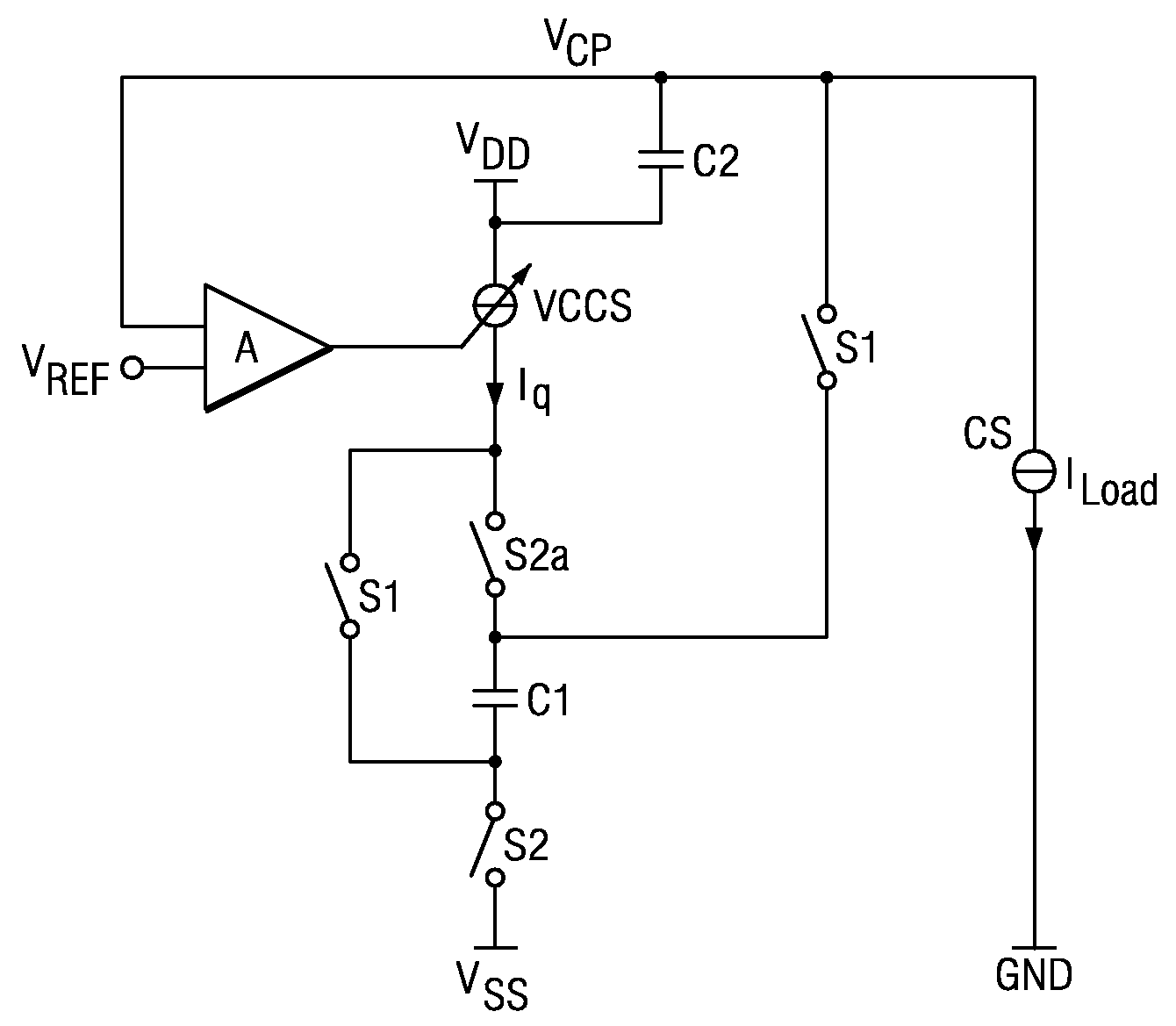
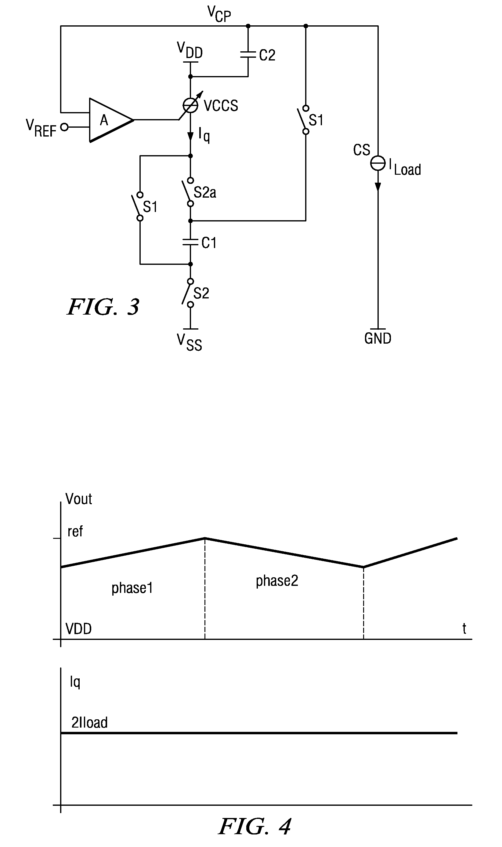
[0019]FIG. 3 is a simplified schematic diagram of a charge pump according to the present invention. Capacitor C1 is the flying capacitor which is alternately switched between either VDD and VSS, the ground potential, or between VDD and VCP to charge storage capacitor C2. The output load is represented by a constant current source CS having a constant load current ILoad. The two switches S1 operate synchronously in alternation with switches S2 and S2a. The switching of S2a may be a bit different from S2 in order to avoid unwanted switching effects. During the first phase, switches S2 and S2a are closed and C1 is charged via VCCS. During the second phase S2 are S2a are opened and switches S1 are closed. In the second phase, flying capacitor C1 is coupled to storage capacitor C2 and discharges to C2. Both the charging and the discharging currents are controlled by current source VCCS. Accordingly, the voltage across C1 depends on the duration of the charging and discharging phases and ...


PUM


Abstract

A charge pump for generating an input voltage for an operational amplifier includes a storage capacitor for storing a charge pump voltage and a flying capacitor configured to be charged during a first phase of operation and discharged during a second phase of operation. Discharging the flying capacitor charges the storage capacitor. A current source supplies the flying capacitor and a switching means switches current from the current source through the flying capacitor in a first direction during the first phase and in a second opposite direction during the second phase.

Description

CLAIM OF PRIORITY[0001]This application claims priority under 35 U.S.C. 119(e)(1) to U.S. Provisional Application No. 6 / 016,676 filed Dec. 26, 2007 and under 35 U.S.C. 119(a) to German Patent Application No. 10 2007 020 999.3 filed May 4, 2007.TECHNICAL FIELD OF THE INVENTION[0002]The technical field of this invention is a charge pump used to generate voltages above the power supply voltage.BACKGROUND OF THE INVENTION[0003]A truly rail to rail input operational amplifier with a PMOS or PMP input stage requires a bootstrap or charge pump voltage above the supply voltage. Any noise and ripples of the charge pump voltage especially at high frequencies leak to the operational amplifier output due to a mismatch of input devices, such as parasitic capacitance etc.[0004]FIGS. 1A and 1B are simplified schematics of a conventional charge pump circuit. The negative terminal of capacitor C1 is switched between a positive supply voltage rail VDD and ground and the positive terminal is switched ...

Claims


Application Information

Patent Timeline
IPC IPC(8): G05F1/10
CPCH01L27/0222H02M3/07H03F3/70H03K17/161H03K17/6871H03K17/6872
Inventor IVANOV, VADIM V.GERBER, JOHANNESVANSELOW, FRANK
Owner TEXAS INSTR INC
Why Eureka
Try Eureka