Electrochromic unit and stereo image display device having the same

a stereo image display device and electrochromic technology, applied in non-linear optics, instruments, optics, etc., can solve the problems of unfavorable application of electrochromic modules, increased thickness, and increased etc., to improve the difference of optical transmittance, increase the thickness of electrochromic modules, and enhance the life cycle

Inactive Publication Date: 2012-04-05
J TOUCH CORPORATION
View PDF9 Cites 36 Cited by
  • Summary
  • Abstract
  • Description
  • Claims
  • Application Information

AI Technical Summary

Benefits of technology

[0013]In view of the aforementioned shortcomings, the inventor of the present invention based on years of experience in the related industry to conduct extensive researches and experiments, and finally developed an electrochromic module in accordance with the present invention, in hope of achieving the effects of simplifying the manufacturing procedure and improving the difference of optical transmittances without increasing the thickness.
[0015]Another objective of the present invention is to provide an electrochromic module with a quick coloration / decoloration, a long life cycle, and a small driving voltage.
[0029]Since the first electrically conductive element and the second electrically conductive element provide different positive and negative voltages and can expedite the coloration / decoloration of the electrochromic layer and the ion layer, and limit the range of color change of the electrochromic layer and the ion layer.
[0033]Therefore, the electrochromic module and the stereo image display device of the present invention can improve the difference of the optical transmittance without increasing the thickness of the electrochromic module and the stereo image display device and achieve the effects of expediting the coloration / decoloration, enhancing the life cycle and requiring a small driving voltage.

Problems solved by technology

As a result, the thickness of the electrochromic module 1 will be increased, and the increased thickness is unfavorable for the application of the electrochromic module 1.
Both Pat. Nos. M368088 and M371902 have a common drawback of lacking a necessary electrolyte layer required by electrochromic devices, since ions are not supplied to the electrolyte layer of the electrochromic layer, and the electrochromic device cannot produce a reversible oxidation or reduction to complete the change of coloration or decoloration, so that the aforementioned patents are not feasible in practical applications.
In addition, the transparent electrode layer and electrochromic material layer of the parallax barrier device are grid patterned, and whose manufacturing process requires a precise alignment for coating, spluttering or etching each laminated layer, and thus the manufacturing process is very complicated, and all laminated layers are grid patterned, so that a hollow area is formed between one grid and the other, and the overall penetration, refraction and reflection of the light will be affected adversely.
Even for the general 2D display, the video display quality of the display device will be affected to cause problems related to color difference and uneven brightness.
In addition, the structural strength of the display device is low, and the using life is short.
The Pat. No. 1296723 disclosed an embedded liquid display device (LCD) formed in a structure of a color filter plate, and conventional electrochromic materials and chromic mechanisms are adopted for the electrochromic layer of the aforementioned patents and thus requiring a greater driving voltage, causing a defect of the material easily, and resulting in a shorter using life.

Method used


Image

  • Electrochromic unit and stereo image display device having the same
  • Electrochromic unit and stereo image display device having the same
  • Electrochromic unit and stereo image display device having the same

Examples


Embodiment Construction

[0063]The technical characteristics and effects of the present invention will be apparent with the detailed description of preferred embodiment together with the illustration of related drawings as follows.

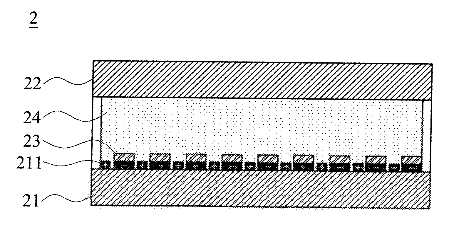
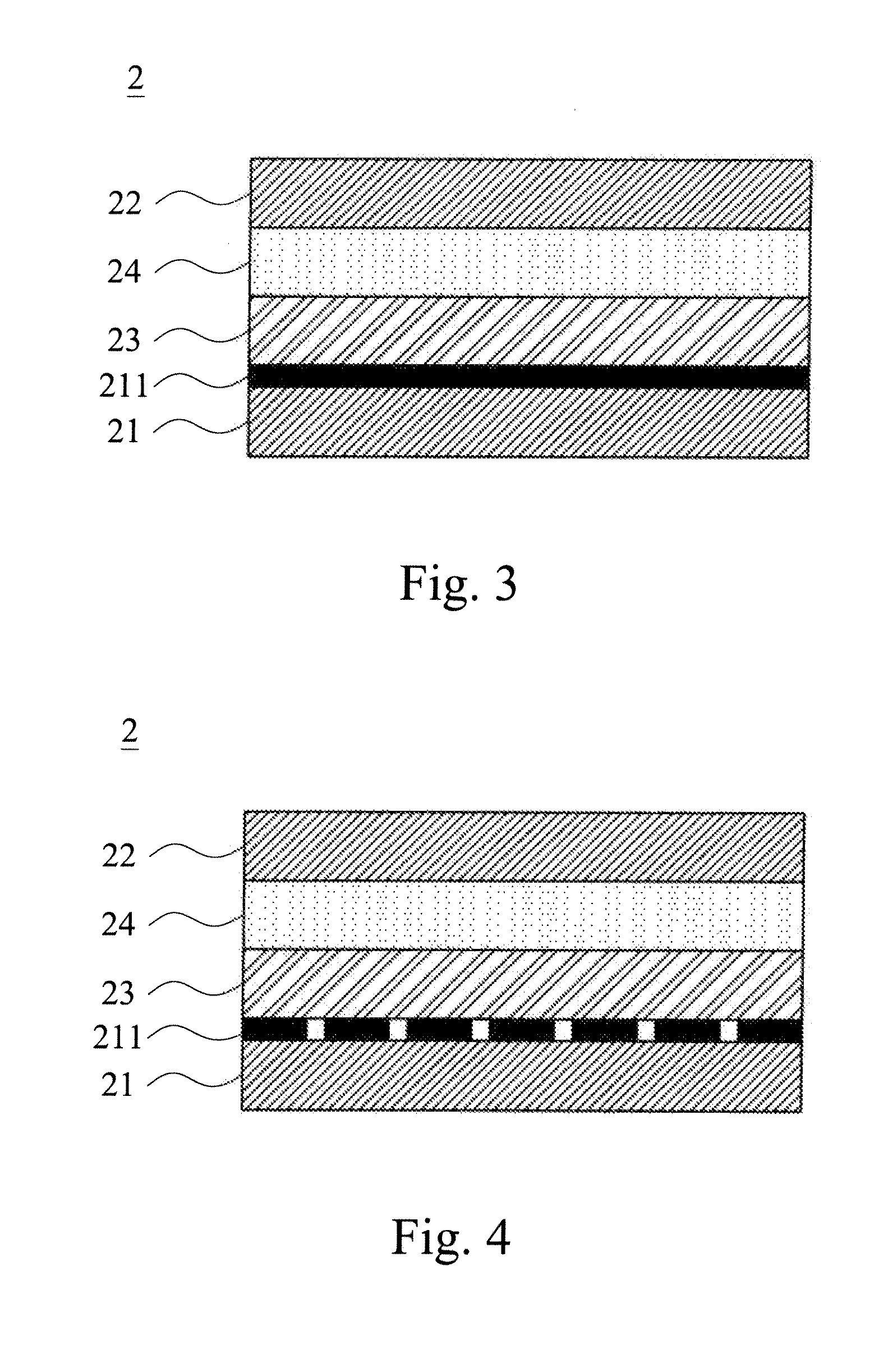
[0064]With reference FIG. 3 for a schematic view of an electrochromic module in accordance with a first preferred embodiment of the present invention, the electrochromic module 2 comprises a first substrate 21, a second substrate 22, an electrochromic layer 23 and an ion layer 24. The first substrate 21 includes a first electrically conductive element 211 disposed at an upper surface of the first substrate 21. The electrochromic layer 23 is disposed between the first substrate 21 and the second substrate 22. The ion layer 24 is disposed on a surface of the electrochromic layer 23 and grounded, and whose material is prepared by mixing and dissolving at least one or more organic material and at least one or more inorganic material into a solvent.

[0065]Therefore, when a positive volt...


PUM

PropertyMeasurementUnit
light transmittanceaaaaaaaaaa
electrically conductiveaaaaaaaaaa
electrochromicaaaaaaaaaa

Abstract

In an electrochromic module and a stereo image display device having the electrochromic module, the electrochromic module includes a first substrate, a second substrate, at least one electrochromic layer and at least one ion layer. The first substrate upper surface includes at least one first electrically conductive element disposed between the first substrate and the second substrate. The ion layer is formed on a surface of the electrochromic layer and prepared by mixing and dissolving at least one organic material and at least one inorganic material in a solvent. The ion layer not only serves as an ion provider, but also acts as an electrochromic material of an accessory color change layer for improving the difference of the optical transmittance. By the shifting and transmission of electrons between the organic and inorganic materials, the electrochromic module has the advantages of fast and uniform color change and smaller driving voltage.

Description

CROSS-REFERENCE TO RELATED APPLICATIONS[0001]This non-provisional application claims priority under 35 U.S.C. §119(a) on Patent Application No(s). 099133877 filed in Taiwan, R.O.C. on Oct. 5, 2010, the entire contents of which are hereby incorporated by reference.BACKGROUND OF THE INVENTION[0002]1. Field of the Invention[0003]The present invention relates to an electrochromic unit and a stereo image display device having the electrochromic unit, and more particularly to an electrochromic unit and a display device having the electrochromic unit, and an electrochromic material is used as an ion layer for providing ions to an electrochromic layer, and the ion layer is prepared by mixing at least one organic material with at least one inorganic material in a solvent.[0004]2. Description of the Related Art[0005]Electrochromism (EC) refers to a reversible color change caused by a light absorption or a light diffusion occurred in an electrochromic material under the effect of a current or ...

Claims


Application Information

Patent Timeline
Patent Type & Authority Applications(United States)
IPC IPC(8): G02F1/153
CPCG02F2001/1519G02F1/1525G02F2001/164
Inventor YEH, YU-CHOUWANG, CHAO-YILO, WEN-CHIHSUNG, CHI-HSIENYEH, TSUNG-HER
Owner J TOUCH CORPORATION
Why Eureka
Try Eureka