Method and apparatus for component recognition

a component recognition and component technology, applied in metal working apparatus, instruments, manufacturing tools, etc., can solve the problems of small number of pixels, high cost, and difficulty in recognizing clearly, and achieve the effect of removing the difference in image lightness

Inactive Publication Date: 2006-05-23
GK BRIDGE 1
View PDF10 Cites 20 Cited by
  • Summary
  • Abstract
  • Description
  • Claims
  • Application Information

AI Technical Summary

Benefits of technology

[0049]According to a fifteenth aspect of the present invention, there is provided a component recognition method as defined in any one of the twelfth to fourteenth aspects, wherein when the image pickup conditions are adjusted, image signal gain is adjusted so as to be suited for image recognition based on the component information of the component to eliminate difference in lightness of the image to be picked up due to difference in performance between the first image pickup unit and the second image pickup unit and kind of the component.

Problems solved by technology

This is, for example, because if the optical system mounted on the second camera is changed to enlarge the image pickup range, the small number of pixels thereof disturbs clear recognition of individual terminals (pins and balls) in an electronic component.
However, this complicates structure and brings about high costs, and size of the image pickup unit itself becomes large and heavy, thereby causing an issue of susceptibility to influence of mechanical vibration.

Method used


Image

  • Method and apparatus for component recognition
  • Method and apparatus for component recognition
  • Method and apparatus for component recognition

Examples


Embodiment Construction

[0086]Before description of the present invention proceeds, it is to be noted that like parts are designated by like reference numerals throughout the accompanying drawings.

[0087]A first embodiment of the present invention will be described hereinafter in detail with reference to drawings.

[0088]Embodiments of the present invention will be described hereinafter in detail with reference to drawings.

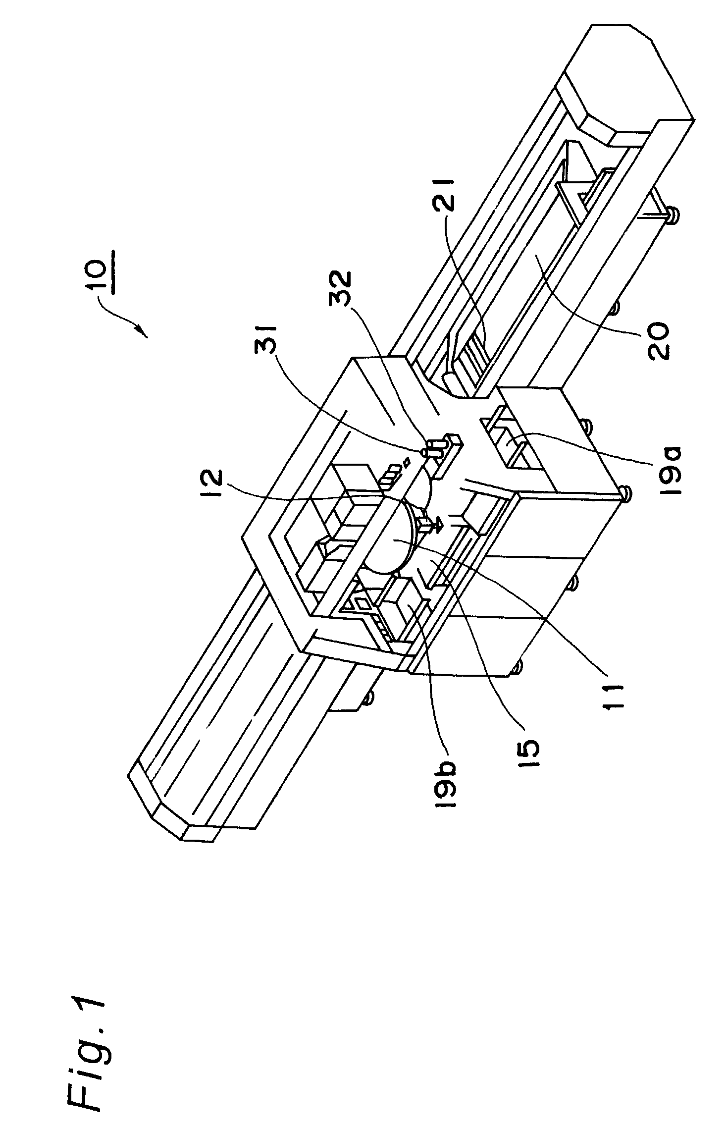
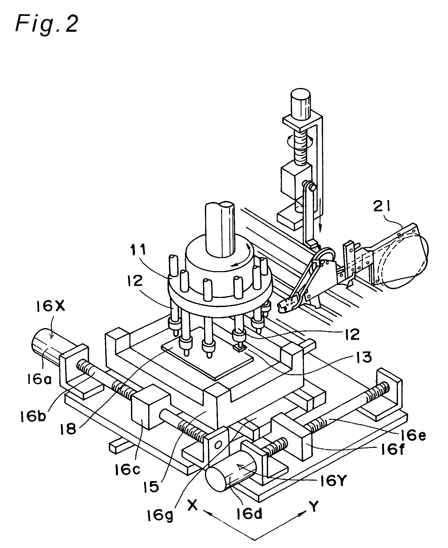
[0089]FIG. 1 is a perspective view showing an appearance of an electronic component mounting apparatus having a component recognition device according to one embodiment of the present invention, FIG. 2 is a view showing an electronic component mounting mechanism in a central portion of the electronic component mounting apparatus of FIG. 1, FIG. 3 is a view showing a rotary index table portion in the electronic component mounting mechanism of FIG. 2 seen from above, FIGS. 4A and 4B are an external view and a schematic plan view each showing a component recognition device of FIG. 3 and a layo...


PUM

PropertyMeasurementUnit
side lengthaaaaaaaaaa
sizeaaaaaaaaaa

Abstract

Adjustment of image pickup conditions through alternative selection of two cameras different in resolution, adjustment of image lightness of a to-be-recognized component based on component information of the component, and performing control allows an image of the component to be picked up by either one of the cameras under the image pickup conditions.

Description

TECHNICAL FIELD[0001]The present invention relates to a component recognition device and a method thereof for image recognition of components, especially electronic components, in a case where the electronic components are recognized as images and placed on circuit forming bodies, as well as to a component mounting apparatus including the component recognition device and a component mounting method including the component recognition method.BACKGROUND ART[0002]FIG. 11 is a plan view showing a main part of a conventional component mounting apparatus, FIG. 12 is a enlarged cross sectional view showing an image pickup unit of FIG. 11, and FIG. 13 is a schematic timing chart showing operation of each section in response to rotation of a rotary index table shown in FIG. 11. On a periphery of rotary index table 111 (hereinafter referred to as index table 111), suction nozzles 112 are installed.[0003]A component feeding section 120 feeds each of a plurality of electronic component feeding ...

Claims


Application Information

Patent Timeline
Patent Type & Authority Patents(United States)
IPC IPC(8): G06K9/00H05K13/08
CPCH05K13/08Y10T29/53178H05K13/0813
Inventor FUKUDA, SHOZOKANETAKA, IWAONOUDO, AKIRAHACHIYA, EIICHI
Owner GK BRIDGE 1
Why Eureka
Try Eureka