Camouflage device for equipment legs

a technology of camouflage device and equipment legs, which is applied in the field of camouflage devices, can solve the problems of foliage drying out, needing replacement, and impractical camouflage for the long legs of ladder stands, and achieves the effect of quick and easy setup of camouflage equipmen

Inactive Publication Date: 2006-05-30
GEORGE RANDALL D
View PDF17 Cites 26 Cited by
  • Summary
  • Abstract
  • Description
  • Claims
  • Application Information

AI Technical Summary

Benefits of technology

[0007]In view of the above, it is an object of the present invention to provide a camouflage device for use on the framework of a ladder stand or the like. It is another object to provide a camouflage device that can be attached to the framework before it is taken into the field such that setup of the camouflaged equipment is quick and easy. It is also an object to provide a camouflage device that makes use of artificial foliage that is not particularly subject to deterioration. Other objects and features of the invention will be in part apparent and in part pointed out hereinafter.

Problems solved by technology

However, since the paint is in effect, two dimensional, it does nothing to break up the outline of the stand or rack.
While bundles or sprigs of vegetation may be tied to a tree stand, this form of camouflage is impractical for the long legs of a ladder stand, tripod stand or the like.
Even if permitted, the act of gathering the foliage may scare away the wild life and, if the framework is left in place, the foliage may dry out and need to be replaced.

Method used


Image

  • Camouflage device for equipment legs
  • Camouflage device for equipment legs
  • Camouflage device for equipment legs

Examples


Embodiment Construction

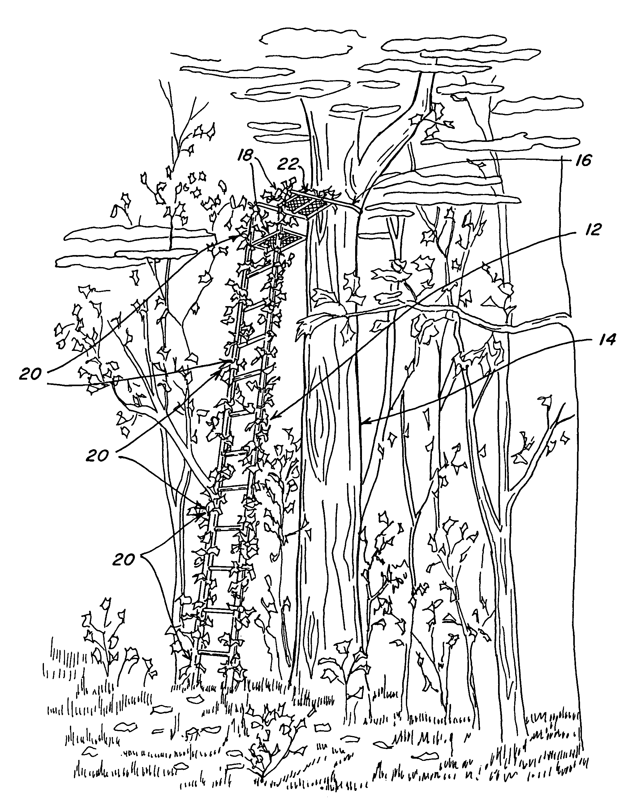
[0018]Referring to the drawings more particularly by reference character, reference numeral 10 refers to a camouflage device in accordance with the present invention. In FIG. 1, device 10 is shown in use camouflaging a hunter's ladder stand 12. Ladder stand 12 is shown attached to a tree 14 with a strap 16. A stabilizer bar (not shown) attached with a second strap may be provided for additional lateral stability.

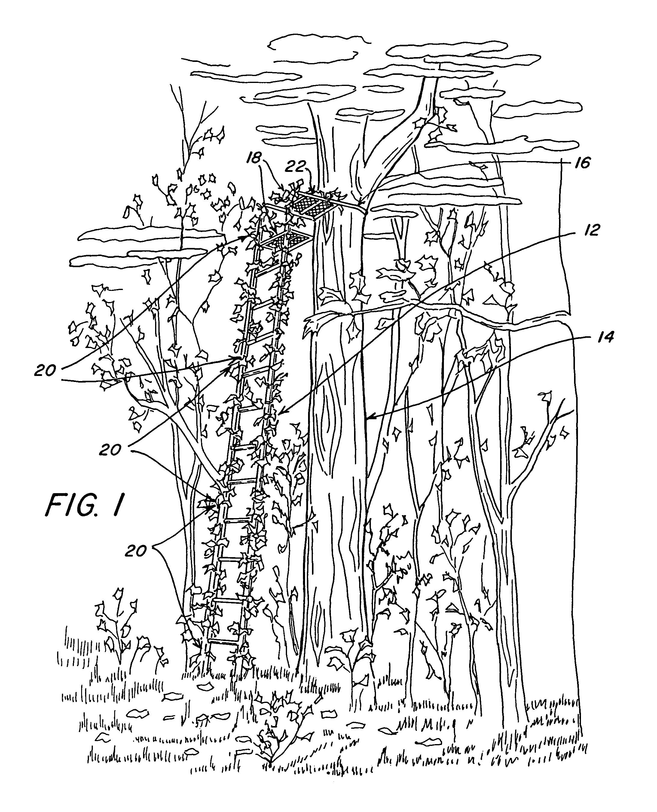
[0019]Ladder stand 12 is preferably formed in sections including a platform section 18 and two or more ladder sections 20. Platform section 18 includes a seat 22 and a footrest 24. Ladder sections 20 include side rails 26 and rungs 28. Typically, ladder sections 20 are about four feet in length and rungs 28 are about 10 inches apart. A twelve-foot or sixteen-foot ladder stand 12 puts platform section 18 at a height where a user does not have to worry about being detected by wary, hunter-wise game. Ladder stand 12 shown in FIG. 1 has three ladder sections 20.

[0020]Side rails ...


PUM

PropertyMeasurementUnit
lengthaaaaaaaaaa
lengthaaaaaaaaaa
diameteraaaaaaaaaa

Abstract

A device for providing three dimensional camouflage to a hunter's ladder stand having a seat, footrest, side rails and a plurality of rungs. The device has a hollow plastic tube with a split and holes through which a plurality of stalks of artificial vegetation are inserted. The split is in the form a groove or has notches so that when the tube is attached to a rail of a ladder stand, the tube does not interfere with the rungs.

Description

BACKGROUND OF THE INVENTION[0001]1. Field of the Invention[0002]The present invention relates to a camouflage device for use on a hunter's ladder stand, tripod stand, tripod feeder and the like having long legs.[0003]2. Brief Description of the Prior Art[0004]A hunter's ladder-stand, tripod stand, tripod feeder, and the like are easily detectable by wild life against a natural background even in dim lighting. Painting the framework with a neutral color or using a random, irregular color treatment in muted browns, greens, and the like has a positive effect in camouflaging the framework. However, since the paint is in effect, two dimensional, it does nothing to break up the outline of the stand or rack.[0005]Three dimensional camouflage, as opposed to two dimensional camouflage, is a more powerful form of concealment. In the past, hunters, photographers and other nature observers have used bundles or sprigs of natural vegetation as camouflage. This works for smaller equipment such as ...

Claims


Application Information

Patent Timeline
Patent Type & Authority Patents(United States)
IPC IPC(8): B32B1/08
CPCF41H3/00Y10T428/139Y10S428/919
Inventor GEORGE, RANDALL D.
Owner GEORGE RANDALL D
Why Eureka
Try Eureka