

Cafeteria tray accumulator
- Summary
- Abstract
- Description
- Claims
- Application Information
AI Technical Summary
Benefits of technology
Problems solved by technology
Method used
Image

Examples
first embodiment
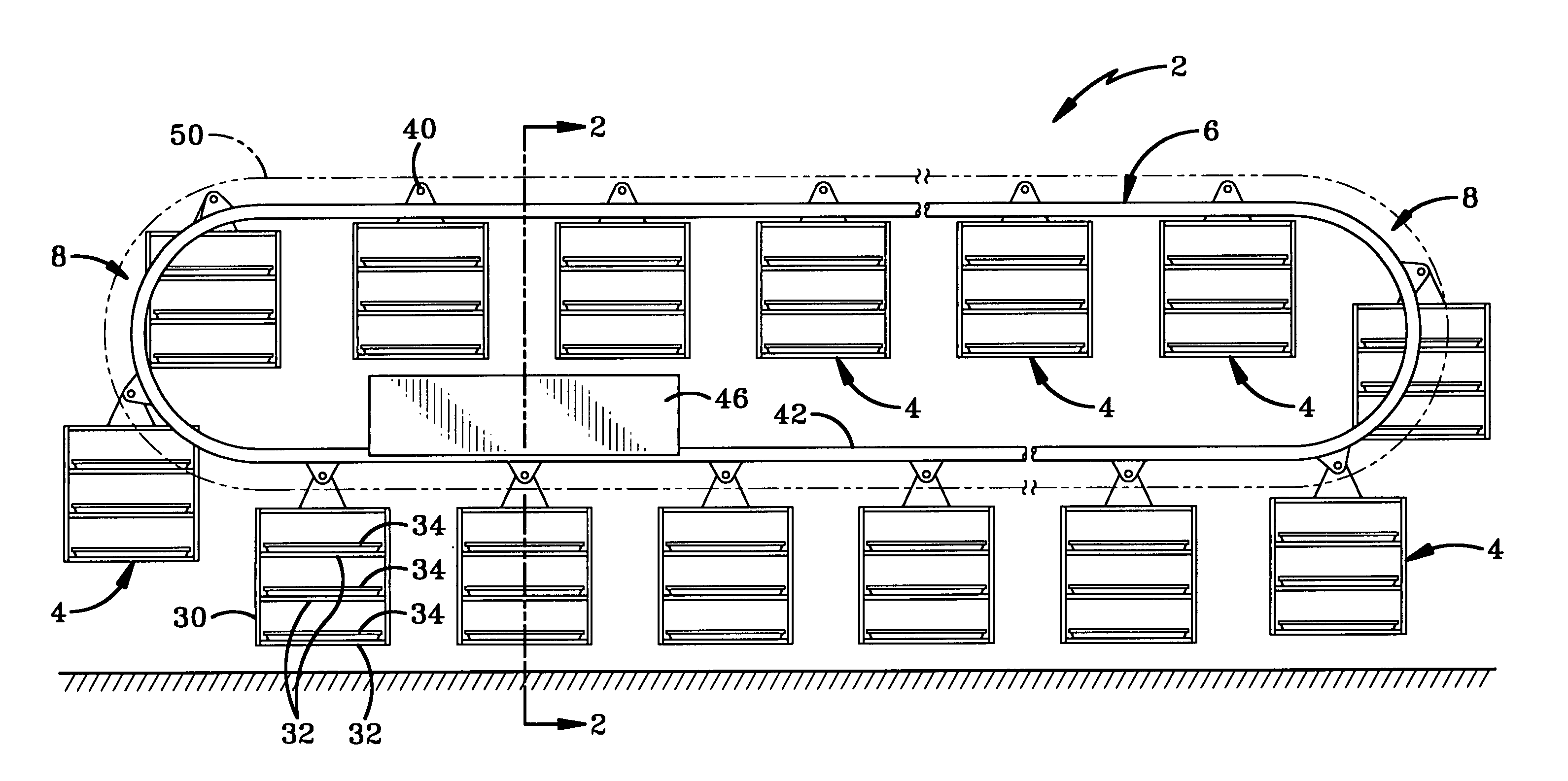
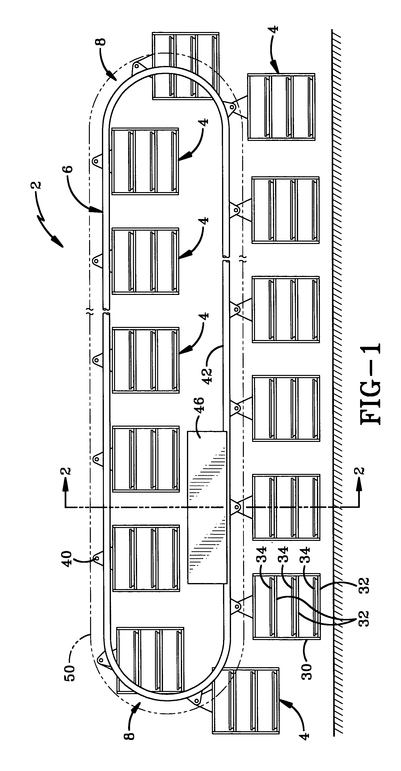
[0023]the tray accumulator of the invention is indicated generally by the number 2 in the accompanying drawings. Tray accumulator 2 generally includes a plurality of tray-holding cages 4 that are suspended from a drive track 6. Drive track 6 follows a looped path having one transverse leg disposed higher than another leg. Each transverse leg may be horizontal as shown in the drawings. In other configurations, the transverse legs may slope up or down. The looped path may be described as an over-up-back or an over-down-back path. The looped path may also be described as a vertically disposed loop or as a loop with its transverse legs offset in a vertical direction. As shown below, the transverse legs may also be offset in a horizontal direction in addition to the vertical direction. In the first configuration, the path has two 180 degree turns 8 where the path moves from one transverse leg to another transverse leg. The path may also traverse horizontal corners to allow for a wide var...
second embodiment
[0034]the tray accumulator of the invention is indicated generally by the numeral 102 in FIGS. 9–11. Tray accumulator 102 uses may of the same elements as tray accumulator 2 described above and the same numbers are used to refer to these elements in FIGS. 9–11. In this embodiment, drive track 6, counterbalance rail 50, and cages 4 are carried by a frame 104 disposed adjacent wall 10. Frame 104 is a self-supporting structure that allows accumulator 102 to be retrofit into existing accumulator spaces with modifications to walls 10 and 12. Frame 104 includes a top deck 106 that covers accumulator 102 and provides rigidity to frame 104. A plurality of legs 108 provide height adjustments. Legs 108 and deck 106 are preferably fabricated from a washable material (aluminum or stainless steel).
[0035]Drive track 6 engages and is driven by drive unit 46 as described above. In this embodiment of the invention, counterbalance rail 50 uses the same structure as drive track 6 but without drive uni...
PUM
 Abstract
Description
Claims
Application Information