Electrical connector having shielding plates

a shielding plate and electric connector technology, applied in the field of electric connectors, can solve the problems of easy breakage of shielding plates, infirmity of shielding plates,

Inactive Publication Date: 2006-05-30
HON HAI PRECISION IND CO LTD
View PDF5 Cites 14 Cited by
  • Summary
  • Abstract
  • Description
  • Claims
  • Application Information

AI Technical Summary

Benefits of technology

[0007]It is an object of the present invention to provide an electrical connector that can attach shielding plates tightly to an insulative housing thereof.

Problems solved by technology

A problem has been found when the basic structure of the low profile connector disclosed in the aforementioned U.S. Patent is applied to the high profile design.
The problem is that because the windows are provided along the upper end of the shield plate, the shielding plate is so infirm and easy to be broken, especially when the complementary connector mates with said connector repeatedly.

Method used


Image

  • Electrical connector having shielding plates
  • Electrical connector having shielding plates
  • Electrical connector having shielding plates

Examples


Embodiment Construction

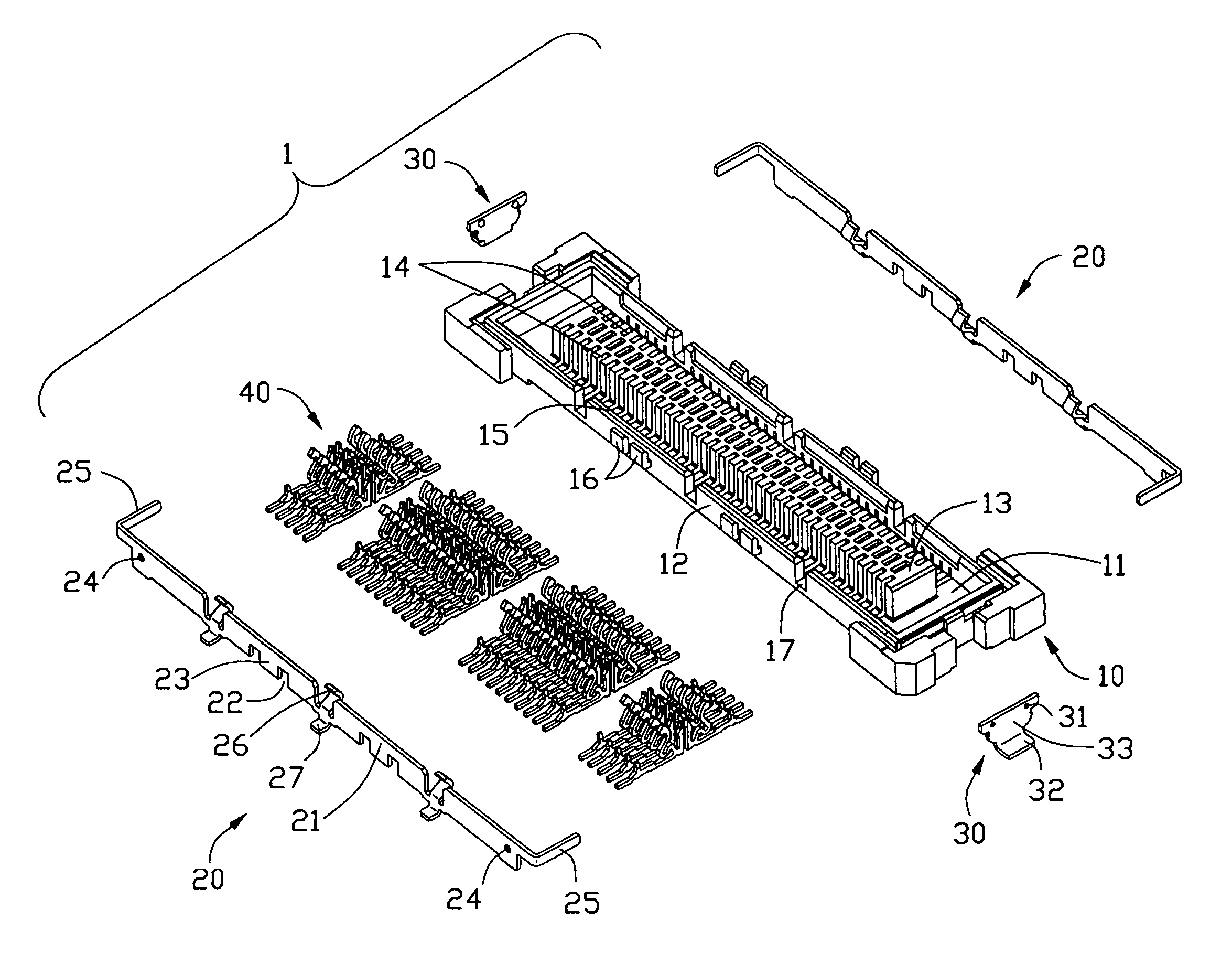
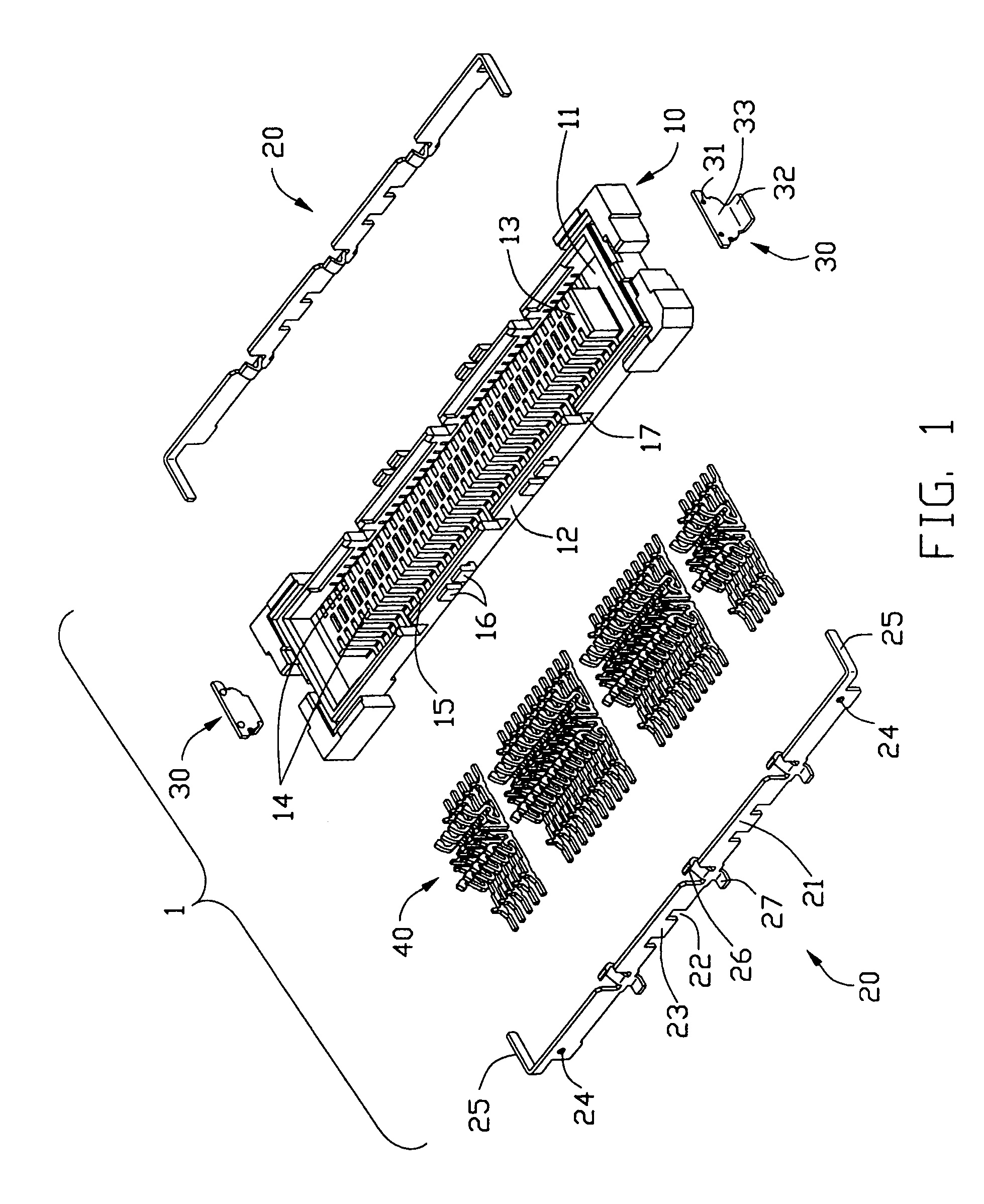
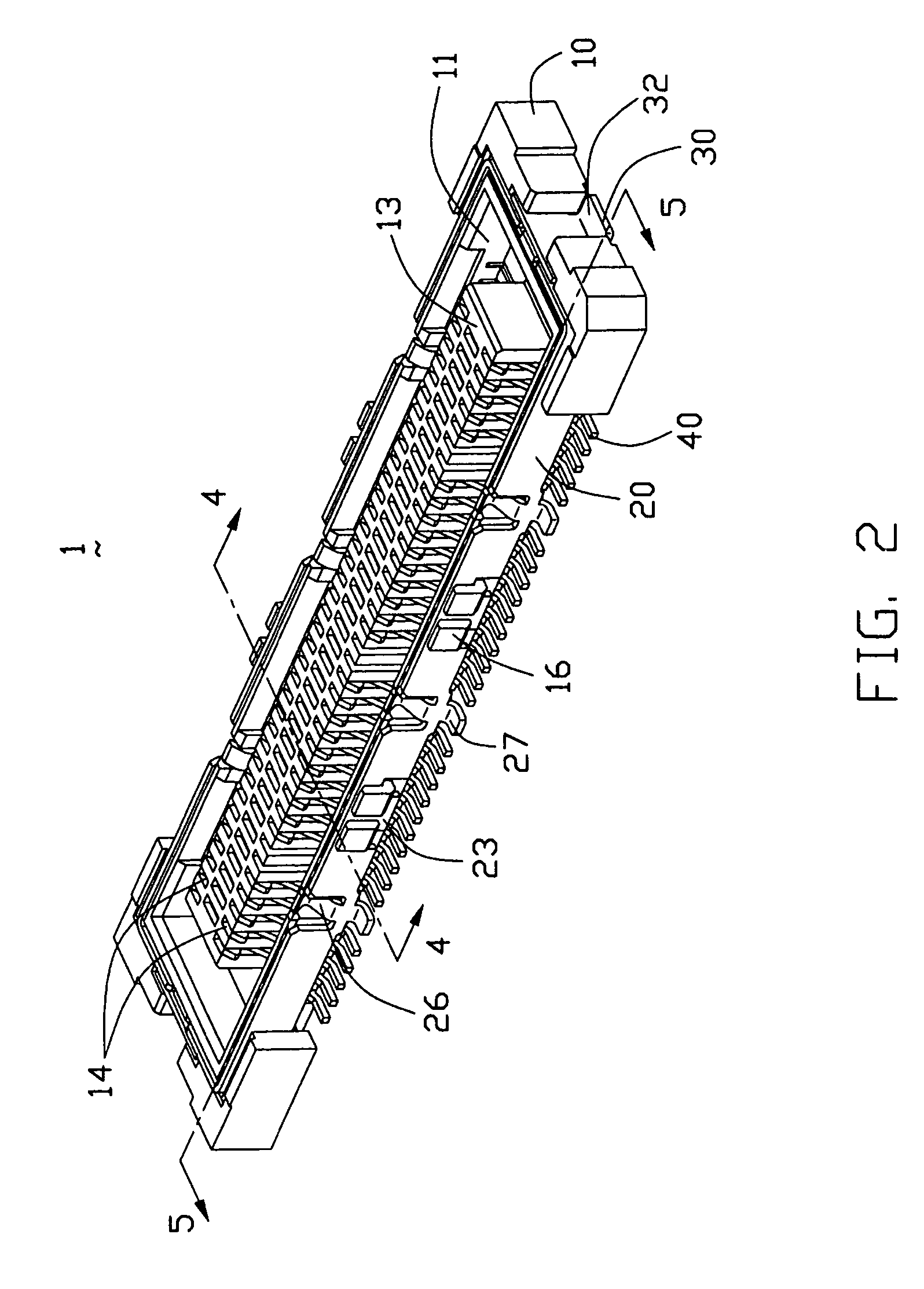
[0014]With reference to FIGS. 1, 2 and 3, an electrical connector 1 in accordance with the present invention comprises an insulative housing 10, a pair of shielding plates 20 attached to longitudinal sides of the housing 10, a pair of reinforcing plates 30 assembled on opposite ends of the housing 10, and a plurality of terminals 40 received in the housing 10.

[0015]The insulative housing 10 comprises a pair of opposite, longitudinal side walls 12, and a tongue section 13 extending between the side walls 12, and defines a receiving space 11 and a plurality of passageways 14 on opposite side of the tongue section 13. Each side wall 12 has a plurality of cutouts 17 defined along an upper edge 15 thereof. A plurality of pairs of retainers 16 extend from outer faces of the side walls 12. Each retainer 16 comprises an engaging portion 162 and a joint portion 161 connecting the side wall 12 and the engaging portion 162. The engaging portions 162 of each pair of retainers 16 extend toward e...


PUM


Abstract

An electrical connector (1) has an insulative housing (10), a number of terminals (40) received in the insulative housing, a pair of shielding plates (20) attached to the sides of the housing and a pair of reinforcing plates (30) assembled on opposite ends of the housing and electrically connecting with the shielding plates. The housing includes a pair of side walls (12), a receiving space (11) defined between the side walls and a number of cutouts (17) defined along upper edges of the side walls. Each shielding plate has an elongated base portion (21) forming a number of spring tabs (26) engaging with the cutouts of the housing and exposed in the receiving space.

Description

BACKGROUND OF THE INVENTION[0001]1. Field of the Invention[0002]The present invention relates to an electrical connector, and particularly to an electrical connector having shielding plates.[0003]2. Description of Prior Arts[0004]U.S. Pat. No. 6,394,841 discloses an electrical connector comprises a plurality of shield plates on two longitudinal sides of an insulative housing and a plurality of reinforcing plates made of metal on two opposite ends of the housing. The shield plates and the reinforcing plates electrically contact with each other. There are a plurality of elongated windows provided along an upper end of the shield plate. A beam portion is formed between both ends of the window and the upper end of the shield plate. The beam portion is flexible in the direction of a thickness of the shield plate. A contact section is provided in the middle of the beam portion to make spring contact with a shielding plate of a mating complementary connector. A plurality of retainers are p...

Claims


Application Information

Patent Timeline
Patent Type & Authority Patents(United States)
IPC IPC(8): H01R13/648H01R12/16H01R13/658
CPCH01R23/6873H01R13/65802H01R13/6582
Inventor ZHANG, CHIZHANG, JERKY
Owner HON HAI PRECISION IND CO LTD
Why Eureka
Try Eureka