Chain guide mechanism

a technology of guide mechanism and chain, which is applied in the direction of belt/chain/gearing, mechanical equipment, belts, etc., can solve the problems of affecting the flow of lubricant to the sprocket, difficult assembly and disassembly process, and time-consuming, so as to achieve adequate lubrication of the sprocket, prevent leakage, and effectively prevent oil leakage

Inactive Publication Date: 2011-10-13
TSUBAKIMOTO CHAIN CO
View PDF10 Cites 10 Cited by
  • Summary
  • Abstract
  • Description
  • Claims
  • Application Information

AI Technical Summary

Benefits of technology

[0020]When the oil inlet of the bridge is connected to an oil supply port on the engine block or supplied with oil through another path, it becomes possible to supply lubricating oil through the oil passage and the oil discharge port directly to the teeth of the sprocket. Therefore, even though the guide bridge is in a position such that it would ordinarily hamper the flow of oil onto the sprocket, it becomes possible to maintain adequate lubrication of the sprocket.
[0021]In a preferred embodiment, a side surface of the base which faces perpendicular to the directions in which the arms extend and also perpendicular to the direction in which the base extends, is provided with a projection. The oil inlet is formed in the projection, and the projection can be provided with a seal for engaging an oil supply port and for preventing leakage of the oil supplied by the oil supply port to the oil inlet. By preventing leakage, the seal ensures an adequate supply of lubricant to the tooth surfaces of the sprocket.
[0022]The seal can be a resilient member that protrudes farther than the projection. The resilient member more effectively prevents leakage of oil by providing a tight seal on the outer circumference of the projection, and by tightly engaging the engine block or other source of oil.
[0023]In an alternative embodiment, the seal can be an annular sealing member fitted to an inner circumferential surface of the projection on the side surface of the base. When the seal is an annular sealing member fitted to the inner circumferential surface of the projection, it is possible to engage the projection of the bridge with an oil supply projection on the engine block while mounting the chain guide mechanism. Accordingly, with this embodiment, assembly and maintenance of the chain guide mechanism can be carried out more efficiently. Moreover, since the projection on the engine block serves as a positioning device it is possible to eliminate other positioning devices.
[0024]In either case, whether the seal protrudes beyond the projection on the guide bridge or is in the form of an annular seal fitted to the inner circumferential surface of the projection, the seal can be a rubber ring. In this case, because the rubber ring tends to adhere to the surfaces which it engages, it more effectively suppresses leakage of lubricant, and further ensures an adequate supply of lubricant to the sprocket.
[0025]In an alternative embodiment, the base can also have an oil-receiving portion for receiving leaking oil, and an oil path, separate from the oil inlet, for directing leaking oil downward into the oil passage. In this embodiment, because leaking oil is directed downward to the oil passage in the guide bridge, it is possible to supply adequate lubricant to the surfaces of the sprocket teeth without tightly attaching the projection of the guide bridge to the engine block or other oil source, and assembly and maintenance of the chain guide mechanism can be carried out more efficiently.

Problems solved by technology

Consequently the process of assembly and disassembly is difficult and time-consuming.
Another problem is that the guide bridge 610 hampers the flow of lubricant to the sprocket S1.

Method used


Image

  • Chain guide mechanism
  • Chain guide mechanism
  • Chain guide mechanism

Examples


Embodiment Construction

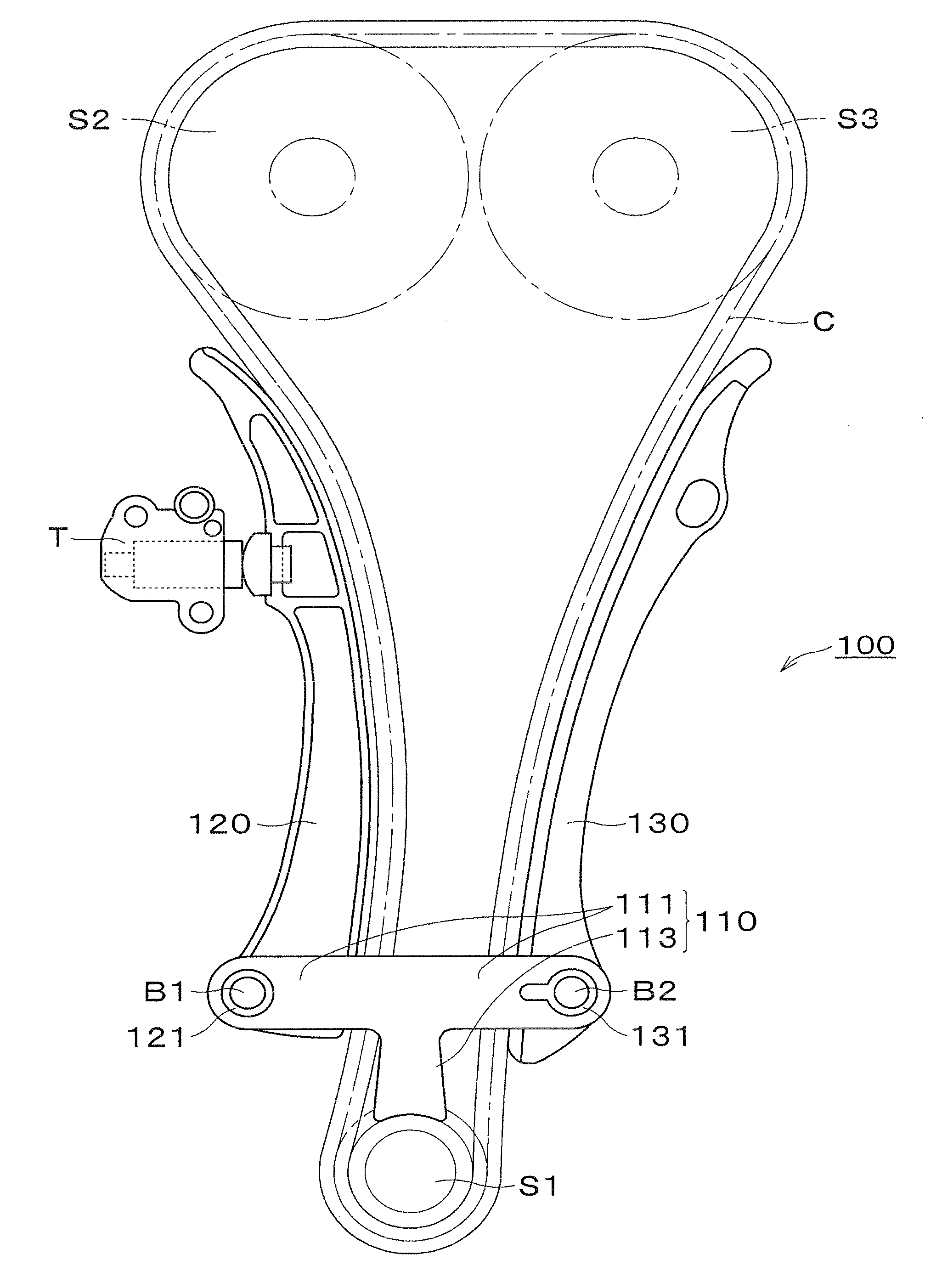
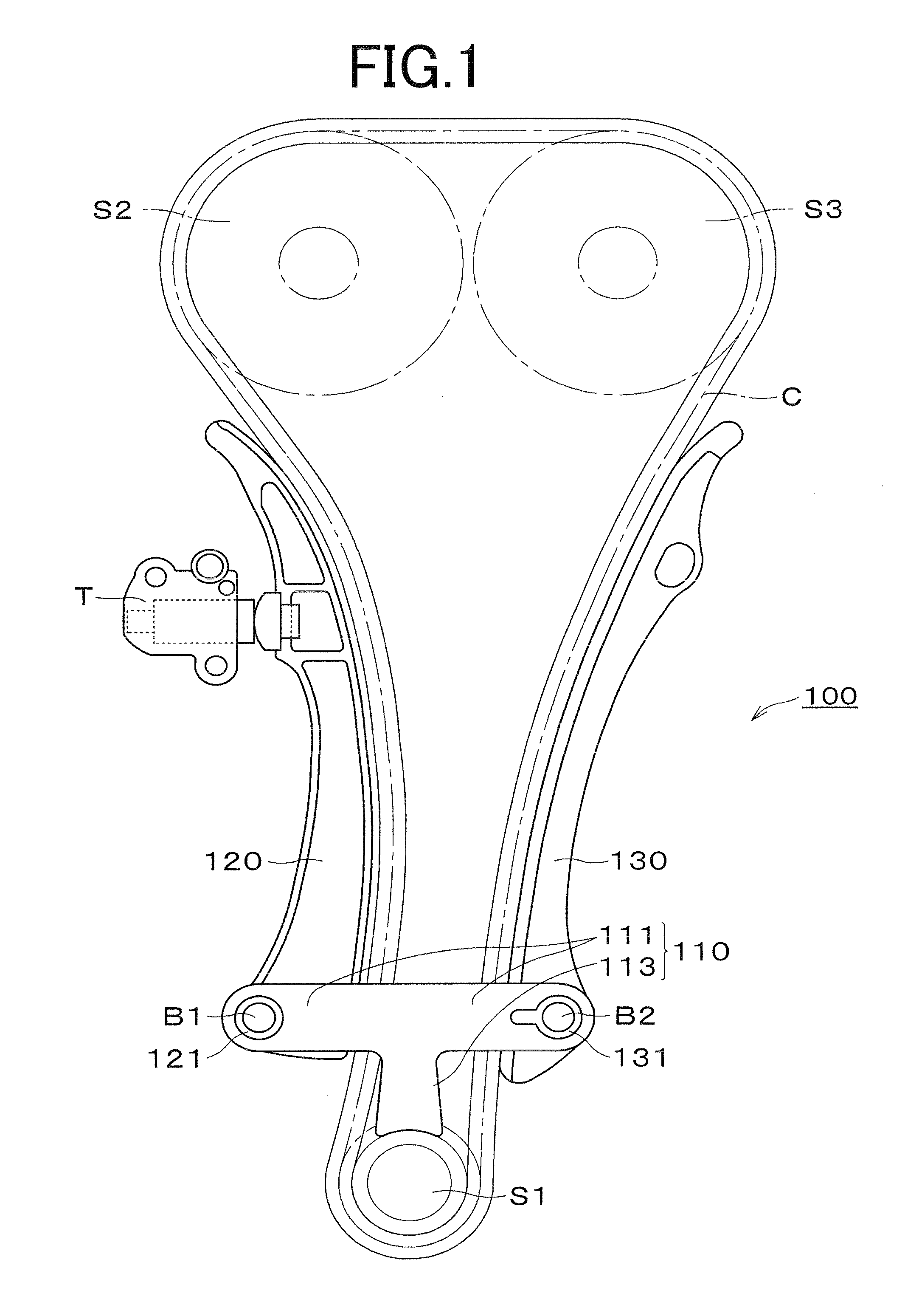
[0041]As shown in FIG. 1, the chain guide mechanism 100 of the invention is used in an engine timing drive in which an endless timing chain C is in driven relationship with an engine crankshaft sprocket S1 and in driving relationship with a pair of camshaft sprockets S2 and S3. The timing drive is typically housed within a space between the engine block and a timing chain cover.

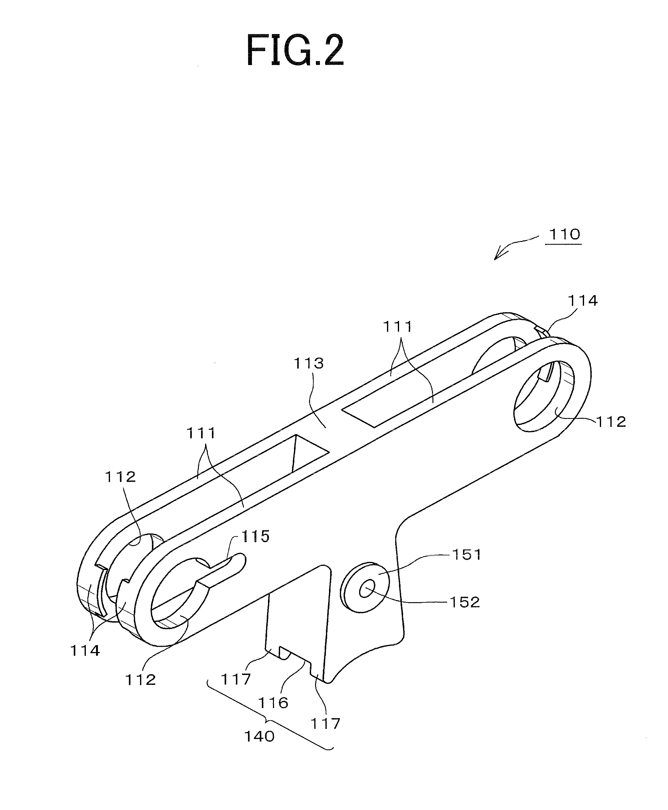
[0042]The chain guide mechanism 100 includes a guide bridge 110 having a pair of arms 111 which extend in opposite directions from a central location, and to which are attached respectively a pivoted chain guide 120, which oscillates with changing tension in the chain C, and a fixed chain guide 130. The bridge also includes a base portion 113 which extends perpendicularly from the oppositely extending arms 111, from the central location between the arms so that the guide bridge is T-shaped. The lower part of the base portion 113 of bridge 110 is in close relationship to the driving sprocket S1.

[0043]The chain...


PUM


Abstract

In a chain guide mechanism having a guide bridge for integrally holding two chain guides, a chain and a driving sprocket for more efficient assembly and maintenance, the guide bridge has a oil inlet on a surface of its sprocket-pressing base for receiving oil from an oil supply port in an engine block on which the guide bridge is mounted. The oil inlet communicates, through an internal passage within the base of the guide bridge, with an oil discharge port within a groove in which teeth of the driving sprocket travel.

Description

CROSS REFERENCE TO RELATED APPLICATION[0001]This application claims priority on the basis of Japanese Patent Application 2010-090665, filed on Apr. 9, 2010. The disclosure of Japanese Patent Application 2010-090665 is incorporated by reference.FIELD OF THE INVENTION[0002]This invention relates to a chain guide mechanism for use in an engine timing drive to guide and maintain tension in an endless timing chain such as a silent chain, a roller chain or the like engaged in driven relationship with a crankshaft sprocket and in driving relationship with one or more camshaft sprockets within a timing drive compartment formed between an engine block and a timing chain cover. The invention relates more particularly to the improvement of lubrication in a chain guide mechanism comprising a plurality of chain guides for sliding engagement with a chain, and a guide bridge for holding the chain guides.BACKGROUND OF THE INVENTION[0003]FIG. 13 shows a known engine timing drive composed of a chain ...

Claims


Application Information

Patent Timeline
Patent Type & Authority Applications(United States)
IPC IPC(8): F16H7/18
CPCF16H7/06F16H7/08F16H2007/0893F16H2007/0806F16H2007/0812F16H7/18
Inventor MORI, KAORIKONNO, MASAHIKO
Owner TSUBAKIMOTO CHAIN CO
Why Eureka
Try Eureka