Transcutaneous inserter for low-profile infusion sets

a low-profile, inserter technology, applied in the field of medical devices, can solve the problems of affecting the flow of insulin, requiring manual dexterity, and kinking of the cannula,

Inactive Publication Date: 2006-05-30
LIFESCAN IP HLDG LLC
View PDF28 Cites 744 Cited by
  • Summary
  • Abstract
  • Description
  • Claims
  • Application Information

AI Technical Summary

Benefits of technology

[0009]According to one aspect of the invention, a low-profile inserter for an angled infusion set comprises an inserter housing having a bottom wall, a retainer slidably connected to the inserter housing for movement between retracted and extended positions in a direction substantially parallel with the bottom wall, and a base member connected to the inserter housing. The retain

Problems solved by technology

While this process is relatively straightforward for more experienced persons, it does require manual dexterity.
In addition, the cannula may become kinked during an improper installation and impede

Method used


Image

  • Transcutaneous inserter for low-profile infusion sets
  • Transcutaneous inserter for low-profile infusion sets
  • Transcutaneous inserter for low-profile infusion sets

Examples


second embodiment

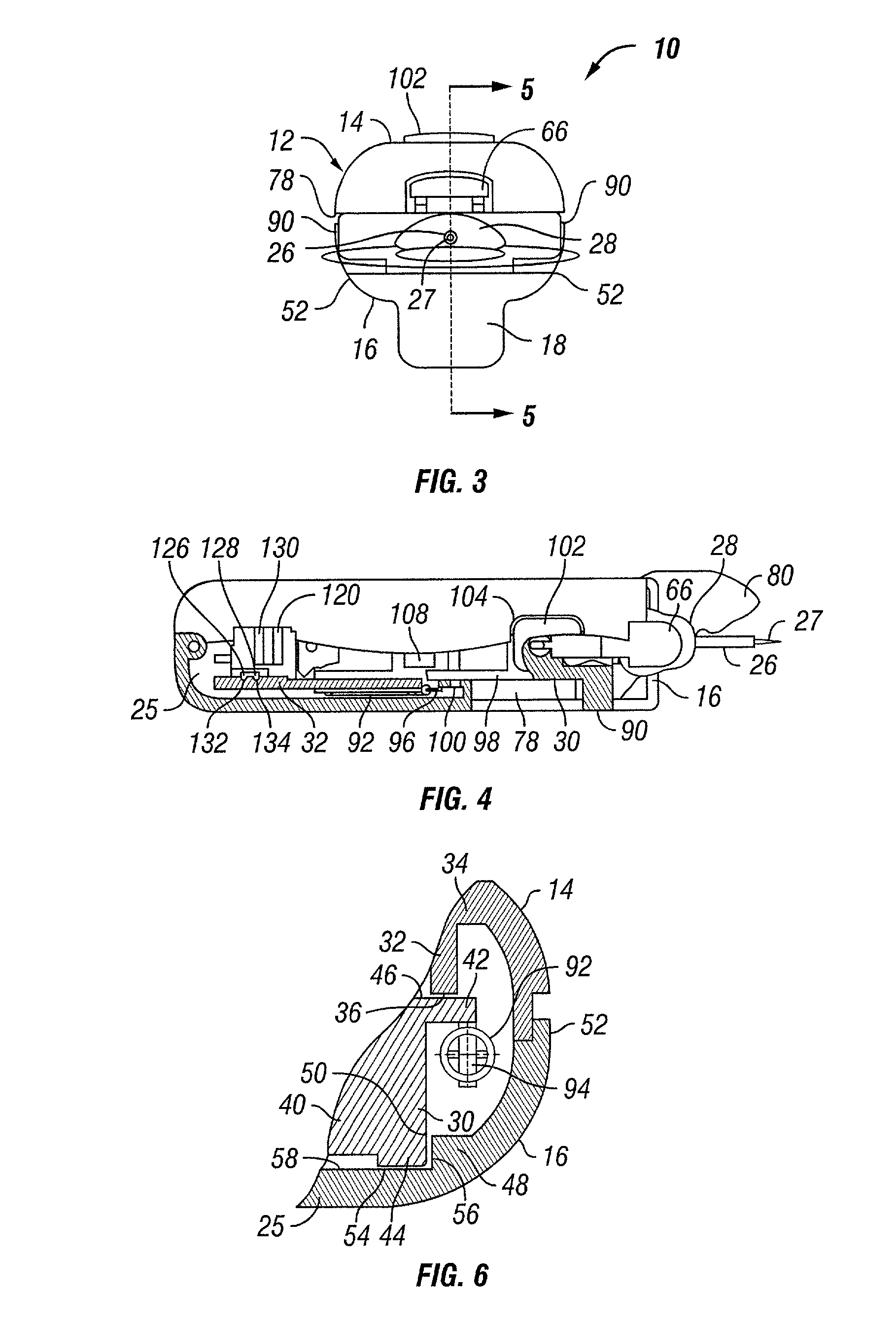
[0036]With reference now to FIGS. 7 and 8, a low-profile inserter assembly 140 according to the invention is illustrated, wherein like parts in the previous embodiment are represented by like numerals. The inserter assembly 140 is similar in construction to the inserter assembly 10, with the exception that an upper housing portion 142 and lower housing portion 144 are narrowed in width behind the release button 102 to form a narrowed handle portion 146 that is easier to hold and manipulate. This narrower width necessitates moving the tension springs 92 (not shown in FIG. 7) inward, closer to the longitudinal centerline of the housing. These springs will now be located under the retainer 30 rather than on each side as shown in FIGS. 4 and 5. However they are attached to the retainer side flange 42 and guide flange 32 of the upper housing portion 142 in a similar manner.

third embodiment

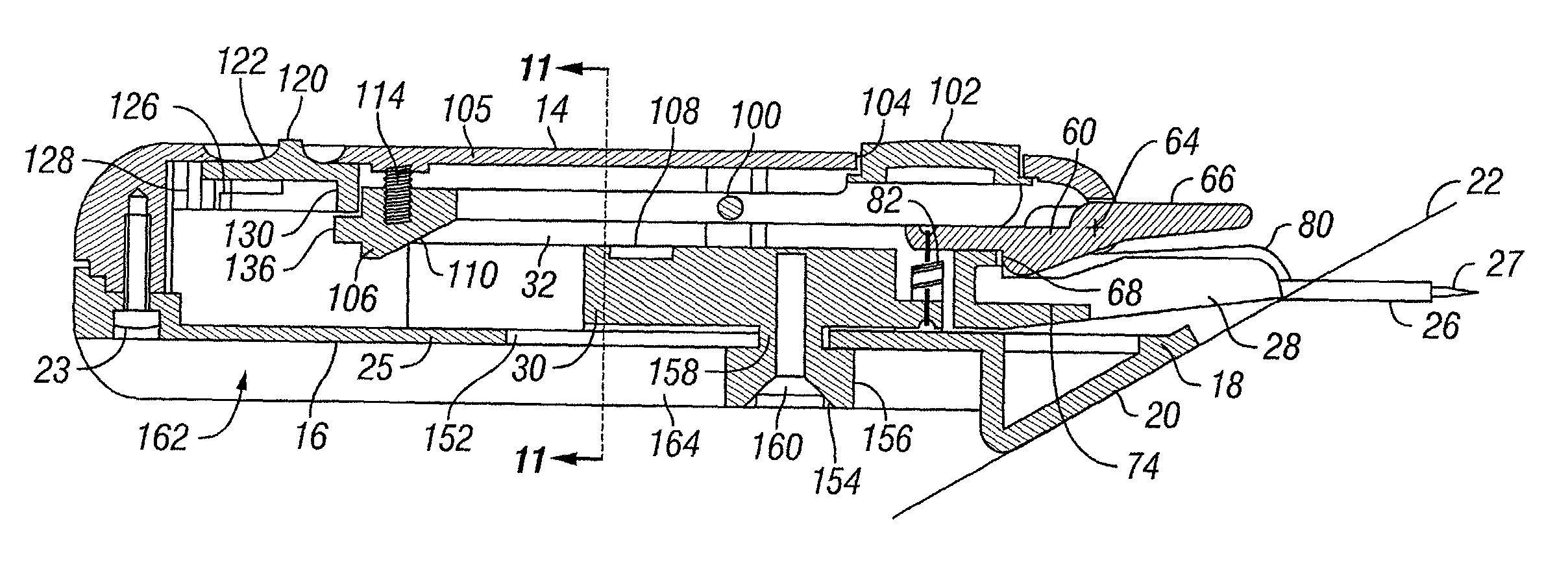
[0037]With reference now to FIGS. 9–11, a low-profile inserter assembly 150 according to the invention is illustrated, wherein like parts in the previous embodiments are represented by like numerals. In this embodiment, a slot 152 is formed in the bottom wall 25 of the lower housing portion 16. A single cocking lever 154 extends downwardly through the slot 152 from the retainer 30. As shown, the cocking lever 154 includes a head portion 156 that is larger than the slot and a neck portion 158 that extends through the slot. The neck portion 158 is preferably integrally formed with the retainer 30. A fastener 160 is countersunk in the head portion 156 and extends through the head and neck portions 156, 158 and into the retainer 30 for securing the head portion to the retainer.

[0038]The bottom wall 25 is formed in a depression 162 of the lower housing portion 16 and is defined by a pair of inner side walls 164 (only one shown in FIG. 9) that extend downwardly from the bottom wall 25. An...

fourth embodiment

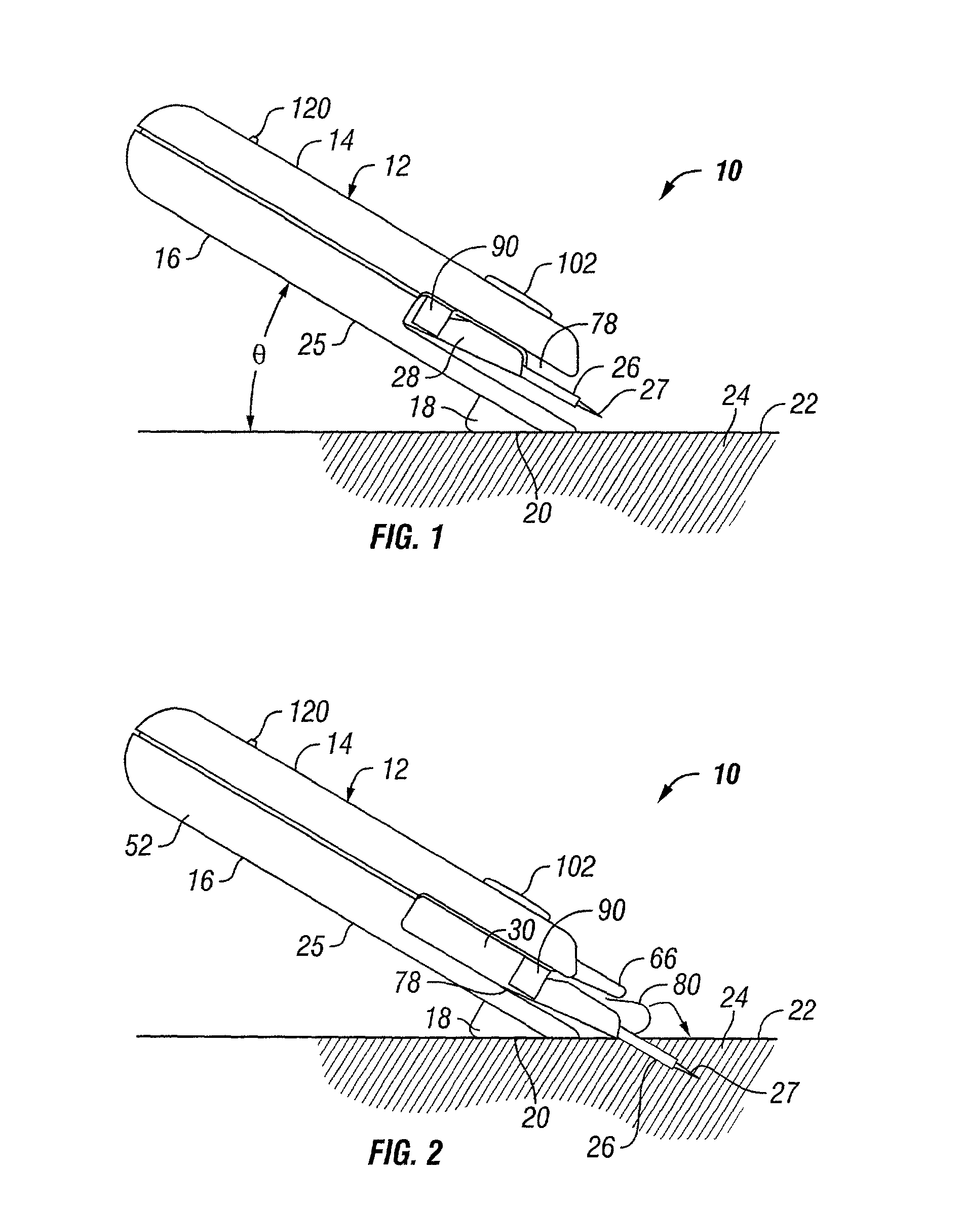
[0040]With reference now to FIGS. 12–14, a low-profile inserter assembly 170 according to the invention is illustrated, wherein like parts in the previous embodiments are represented by like numerals. The inserter assembly 170 includes a housing 172 that is relatively wide in comparison to the previous embodiments. The housing 172 has an upper housing portion 174 connected to a lower housing portion 176 in a manner as previously described. A bifurcated base 178 is preferably integrally formed with the lower housing portion 176 and includes spaced feet 180, 182. Each foot has a lower surface 184 that extends at an acute angle θ with respect to a lower surface 186 of the lower housing portion 176 so that an insertion needle 17 and cannula 26 of a low-profile cannula housing 28 placed in the inserter assembly 170 can be inserted into the skin 24 at the proper angle, as previously described. In one preferred embodiment, the angle θ is approximately 30° to accommodate a cannula that will...


PUM


Abstract

A low-profile inserter for an angled infusion set comprises an inserter housing having a bottom wall, a retainer slidably connected to the inserter housing for movement between retracted and extended positions in a direction substantially parallel with the bottom wall, and a base member connected to the inserter housing. The retainer is adapted to releasably receive a cannula assembly, including a cannula connected to a cannula housing. The base member has a lower surface that is adapted to contact a skin outer surface. The lower surface and bottom wall together form an acute angle. With this arrangement, the cannula can be inserted subcutaneously at the acute angle with respect to the skin outer surface.

Description

CROSS-REFERENCE TO RELATED APPLICATIONS[0001]This application claims the benefit of U.S. Provisional Application No. 60 / 256,573 filed on Dec. 19, 2000.STATEMENT REGARDING FEDERALLY SPONSORED RESEARCH OR DEVELOPMENT[0002]None.REFERENCE TO A MICROFICHE APPENDIX[0003]None.BACKGROUND OF THE INVENTION[0004]This invention relates to medical devices, and more particularly to an automatic inserter for installing an angled or low-profile infusion set in the skin of a person to subcutaneously administer medication or other substances beneficial to health.[0005]Frequent or continuous subcutaneous injection of medication such as insulin is often accomplished through the use of an infusion set or injection port which may remain in place for several days. In the case of frequent injections, the infusion set reduces the need to constantly puncture the skin, thereby minimizing the risk of infection and the formation of scar tissue. For continuous subcutaneous delivery of medication through portable...

Claims


Application Information

Patent Timeline
IPC IPC(8): A61M5/32A61M5/158A61M5/46
CPCA61M5/158A61M5/3287A61M2005/1587A61M2005/1585A61M5/46
Inventor WOJCIK, STEVEN
Owner LIFESCAN IP HLDG LLC
Why Eureka
Try Eureka