Lens array sheet and transmission screen and rear projection type display

a technology of transmission screen and array sheet, which is applied in the field of projection display, can solve the problems of reduced gain, reduced s/n, high cost of material member and material member formation, etc., and achieve the effect of improving contrast and high shading ratio

Inactive Publication Date: 2006-05-30
TOPPAN PRINTING CO LTD
View PDF5 Cites 54 Cited by
  • Summary
  • Abstract
  • Description
  • Claims
  • Application Information

AI Technical Summary

Benefits of technology

[0042]The present invention was made in consideration of the above problems. An object of the present invention is to provided a transparent screen in which there are fewer optical absorption and reduction in the gain (brightness) so as to restrict the white dispersion.
[0043]Furthermore, another object is to provide a transparent screen of which production cost is cheap.
[0074]In a thirtieth aspect of the present invention, a shading pattern (black matrix=BM) is formed according to a “self-alignment method” in which a light condensing section / non-light condensing section forms an aperture section / shading section according to a light condensing characteristics in the lens itself so as to realize a high shading ratio; thus, it is advantageous for improving the contrast.

Problems solved by technology

However, there have been problems such as a reduced gain (brightness) which is caused by a light absorption in the dispersing layer and a reduced S / N ration caused by the increase in a white dispersion.
Also, it is necessary to form a lens in a fine forming operations under condition that it is necessary to used the material member for forming the cylindrical lens twice as many as the conventional case substantially; therefore, there has been a problem that the cost for the material member and the cost for forming the material member are expensive.
However, it is necessary to perform a complicate forming operation and it is difficult to increase an area and perform a fine pitch operation.
Also, productivity is low.
Therefore, the cost increases inevitably.
However, in the above optical dispersing layer, if an optical dispersing agent (particle) is used excessively, there have been problems in that a gain (brightness) is reduced by an optical absorption and an S / N ration is reduced by an increase in a white dispersion.
Therefore, as compared with a CRT transparent projection television, there have been inherent problems in that the brightness of the incident light from the projector is partially high (hot spot), the cylindrical lens may be observed to be bright in a stripe manner in a disposing direction (hot bar), and an unnecessary scintillation which is observed in a projection image may occur frequently.
Furthermore, it is not possible to solve these problems sufficiently only by enlarging the perspective angle in the vertical direction, a hot spot, a hot bar, and a scintillation by enhancing the optical dispersion characteristics by using an optical dispersing agent (particle).

Method used


Image

  • Lens array sheet and transmission screen and rear projection type display
  • Lens array sheet and transmission screen and rear projection type display
  • Lens array sheet and transmission screen and rear projection type display

Examples


first embodiment

[0119]Hereinafter, a first example of the present invention is shown so as to clarify an effect of the present invention.

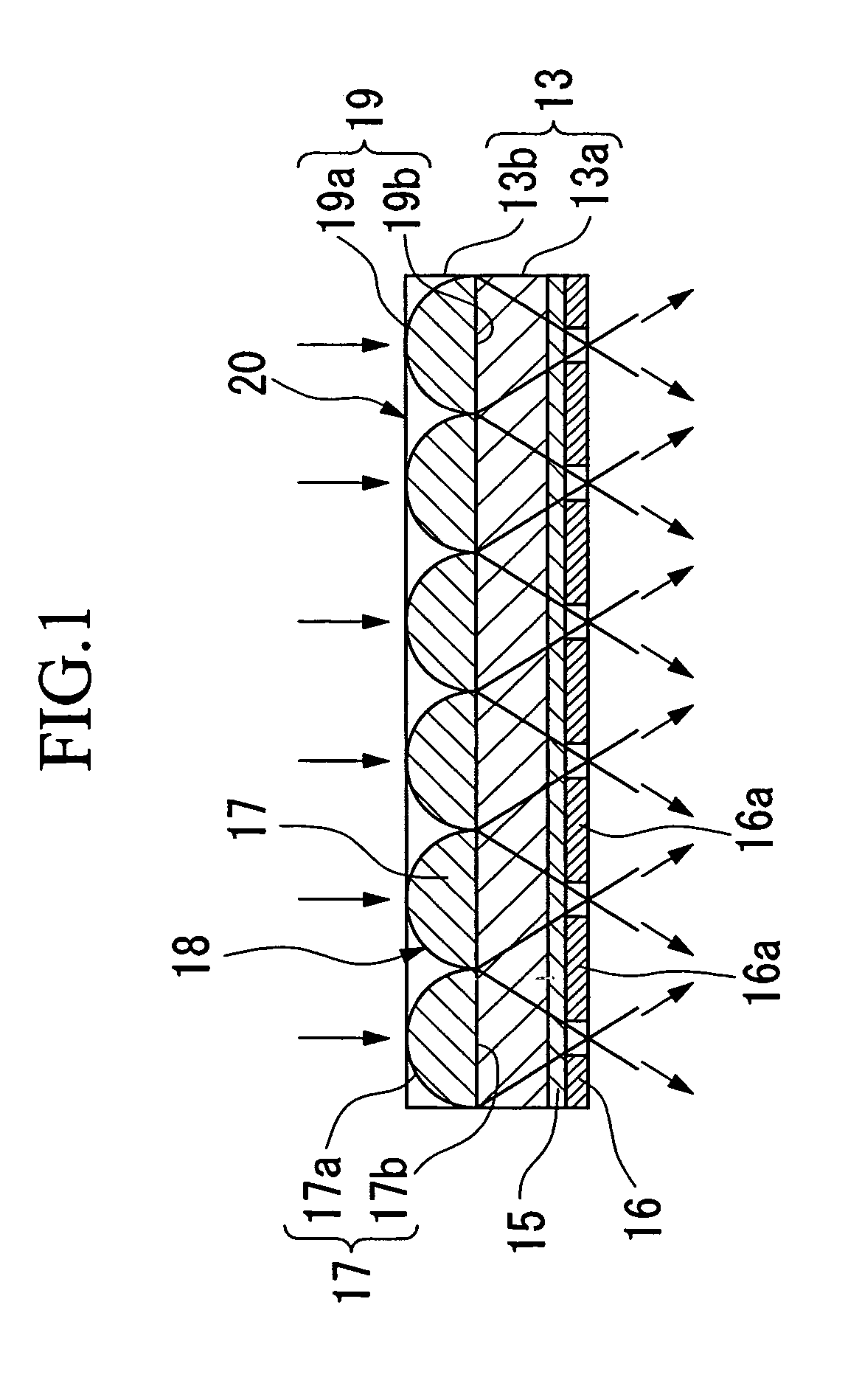
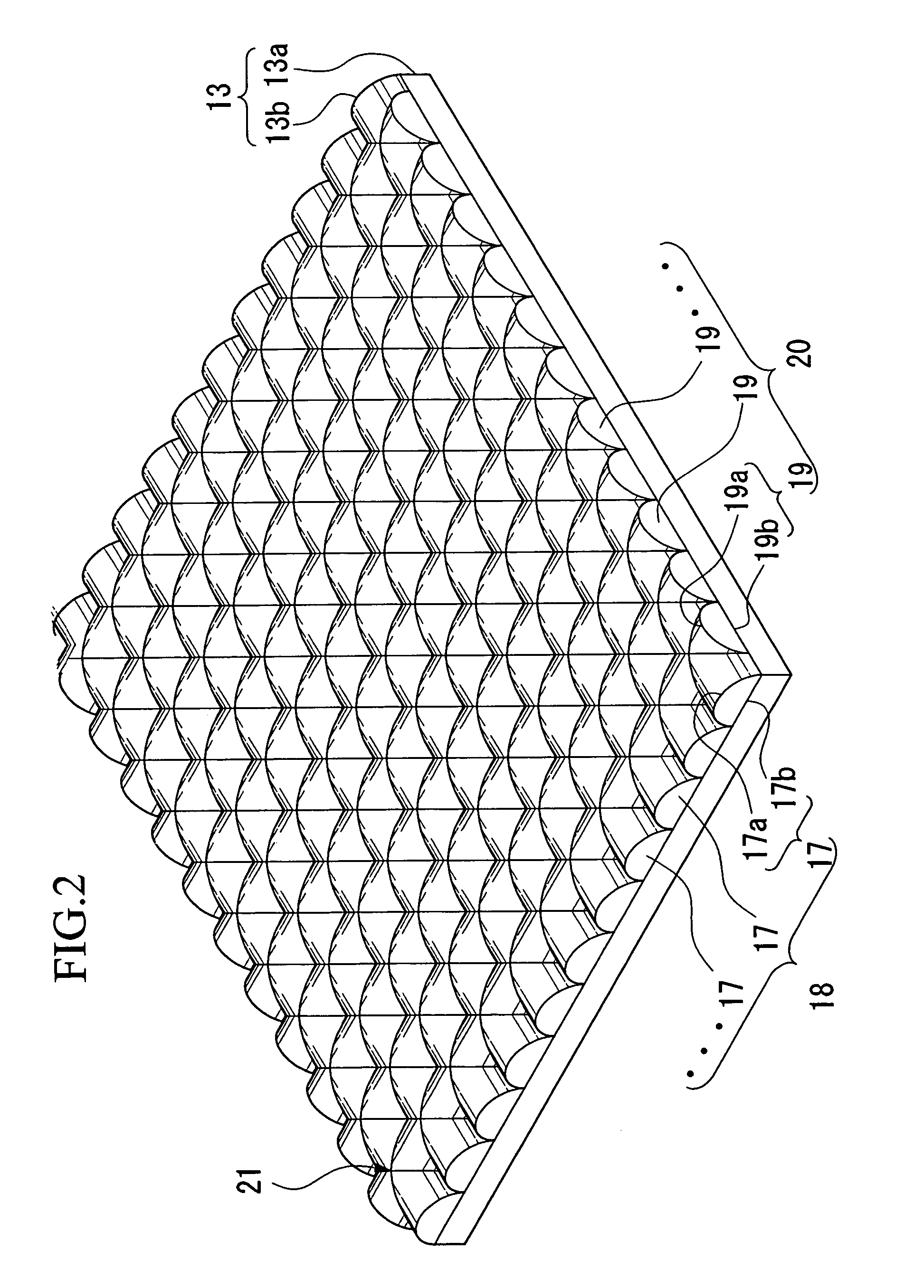
[0120]As explained above, the lens shapes for the lens array sheet shown in FIGS. 1 to 3 are designed. FIGS. 1 to 3 are drawn actually according to the designed shape.

[0121]In the present example, design parameters are determined as follows; thus, an experiment for proving the effect is performed.

(Design Parameters)

[0122](1) In the base member layer for the lens array layer, a material member is a Polyethylene terephthalate, and a thickness is 0.188 mm.[0123](2) In the lens layer for the lens array layer, a material member is an UV photosensitive resin. The lens is formed in an aspherical shape which is formed by adding a higher dimension with reference to a surface an oval surface which has 182 μm pitch.[0124](3) Cromarin (a registered trademark for a product of DUPON) film having 20 μm thickness is used for a photosensitive resin layer.

[0125]That is, a test piec...

second embodiment

[0128]Hereinafter, a detail of the second embodiment of the present invention is explained with reference to drawings as follows.

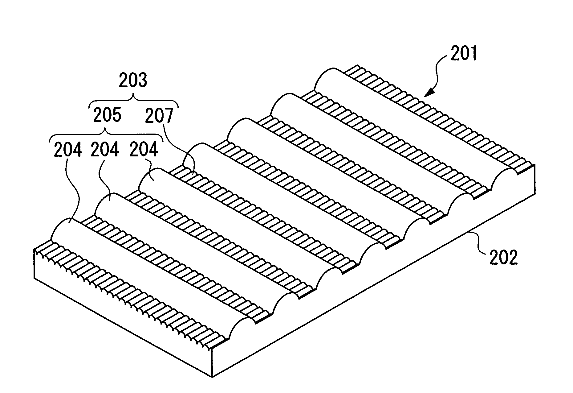
[0129]FIGS. 6 and 7 show an example or the lens array sheet according to the present invention. FIG. 6 is an isometric view for the lens array sheet. FIG. 7 is a cross section. FIG. 8 is a cross section for an important part of a prototype lens array sheet which is produced in an embodiment of the present invention which is explained later in an enlarged manner.

[0130]This lens array sheet 201 is formed by a base member layer 202 which is formed by a transparent material member, and a lens array layer 203 which is disposed on a surface of the base material layer 202. A feature of the present invention resides in a structure of the lens array layer 203.

[0131]In a structure of the above lens array layer 203, a first lens array 205 which is formed by disposing a plurality of cylindrical lenses 204 without intervals therebetween in parallel and a second lens ar...

third embodiment

[0157]Furthermore, a third embodiment of the present invention is explained with reference to drawings.

[0158]FIG. 12 is a view for explaining an example for a structure of a transparent projection screen which relates to a lens array sheet according to an example of the present invention.

[0159]In a structure for the projection screen which is shown in the above drawing, a fresnel lens sheet 390 in which a lens section 392 is disposed on a surface of a base board 391 near a light emitting section and a lens array sheet 380 in which an orthogonal lens section 382 is disposed on a surface (near light emitting section) of a light dispersing base board 382 which is formed by dispersing an optical dispersing agent (particle) is disposed such that mutual lens sections 392, 382 should face each other.

[0160]For such a transparent resin which is used for the base boards 392, 381, it is possible to use, for example, acrylic resin, polycarbonate resin, polyester resin, polyethylene resin, polyo...


PUM


Abstract

A lens array sheet, a transparent screen using the same, and a rear-projection display device are provided in which it is possible to control a perspective angle for the image in both a horizontal direction and a vertical direction without causing a problem in that a gain (brightness) of a light is reduced by an optical absorption and an S / N ratio is reduced by an increased white dispersion.A first lens array 18 and a second lens array 20 which are formed by disposing a plurality of half-cylindrical lenses 17, 19 in parallel on a common plain (a surface of a base member layer 13a) such that longitudinal directions of the cylindrical lenses 17, 19 should be orthogonal to each other. Unified lens array layer 13b and a shading layer 16 in which a section through which a light does not transmit is formed on a focal plain of the lens array layer 13b form a lens array sheet. Furthermore, fresnel lens are combined so as to form a transparent screen.

Description

TECHNICAL FIELD[0001]The present invention relates to a projection display such as a projection television and display. In particular, the present invention relates to a lens array sheet which is suitable for such a usage and a projection screen which uses such a lens array sheet.[0002]It is possible to name a CRT, LCD (liquid crystal display device), DMD (Digital Micro-mirror Device; a trademark registered by Texas Instruments Corp.) for such a representative display such as a projection television in which an image which is emitted from a projector which is provided with various optical engine. In particular, a transparent (projection type, rear-projection type, rear type) projection television is representative.[0003]Hereinafter, the present invention is explained for mainly a transparent projection screen.BACKGROUND ART[0004]A screen is commonly known which is used for a projection television which is provided with a CRT projector having a structure shown in FIG. 10 for one of a...

Claims


Application Information

Patent Timeline
Patent Type & Authority Patents(United States)
IPC IPC(8): G02B27/10G02B3/00
CPCG02B3/0031G03B21/625G02B3/0056G02B3/0037G03B21/62
Inventor YOSHIDA, TSUTOMUEBINA, KAZUYOSHIABE, TAKASHITAKAHASHI, SUSUMU
Owner TOPPAN PRINTING CO LTD
Why Eureka
Try Eureka