Floor treatment system with self-propelled and self-steering floor treatment unit

a floor treatment and self-steering technology, which is applied in the direction of cleaning equipment, application, electric equipment installation, etc., can solve the problems of inability to electrically coupling the respective connecting elements that are associated with one another, and no longer effective power transfer, etc., to achieve facilitate interconnection

Inactive Publication Date: 2006-06-06
ALFRED KARCHER GMBH & CO KG
View PDF7 Cites 239 Cited by
  • Summary
  • Abstract
  • Description
  • Claims
  • Application Information

AI Technical Summary

Benefits of technology

[0009]By spring mounting of at least one of the respective connecting elements that are associated with one another, the electrical coupling of the connecting elements during docking-on of the floor treatment unit at the associated charging station can be improved. A spring mounting of this type has the effect in particular that, when it runs up against the charging station, the floor treatment unit, which is relatively light in comparison with the charging station, is not pushed back from the charging station with the effect that the respective connecting elements are then so far apart from one another that effective power transfer is no longer possible.
[0027]It is advantageous if the charging station comprises a suction-extraction assembly and a dirt receiving container, it being possible during the recharging of the power supply unit for the dirt collecting container to be emptied at the same time by the suction-extraction assembly via the suction inlet. During the docking of the floor treatment unit at the charging station, it is consequently possible not only for power to be transferred for the recharging of the power supply unit of the mobile suction device, but also for the dirt collecting container of the suction device to be emptied.

Problems solved by technology

A spring mounting of this type has the effect in particular that, when it runs up against the charging station, the floor treatment unit, which is relatively light in comparison with the charging station, is not pushed back from the charging station with the effect that the respective connecting elements are then so far apart from one another that effective power transfer is no longer possible.
When the floor treatment unit with a collision detection sensor of this type comes up against the charging station, there is the risk of the impact triggering a collision detection signal and the floor treatment unit subsequently reversing its direction of travel, so that electrical coupling of the respective connecting elements that are associated with one another is not possible.

Method used


Image

  • Floor treatment system with self-propelled and self-steering floor treatment unit
  • Floor treatment system with self-propelled and self-steering floor treatment unit
  • Floor treatment system with self-propelled and self-steering floor treatment unit

Examples


Embodiment Construction

[0038]The ensuing detailed description provides exemplary embodiments only, and is not intended to limit the scope, applicability, or configuration of the invention. Rather, the ensuing detailed description of the exemplary embodiments will provide those skilled in the art with an enabling description for implementing an embodiment of the invention. It should be understood that various changes may be made in the function and arrangement of elements without departing from the spirit and scope of the invention as set forth in the appended claims.

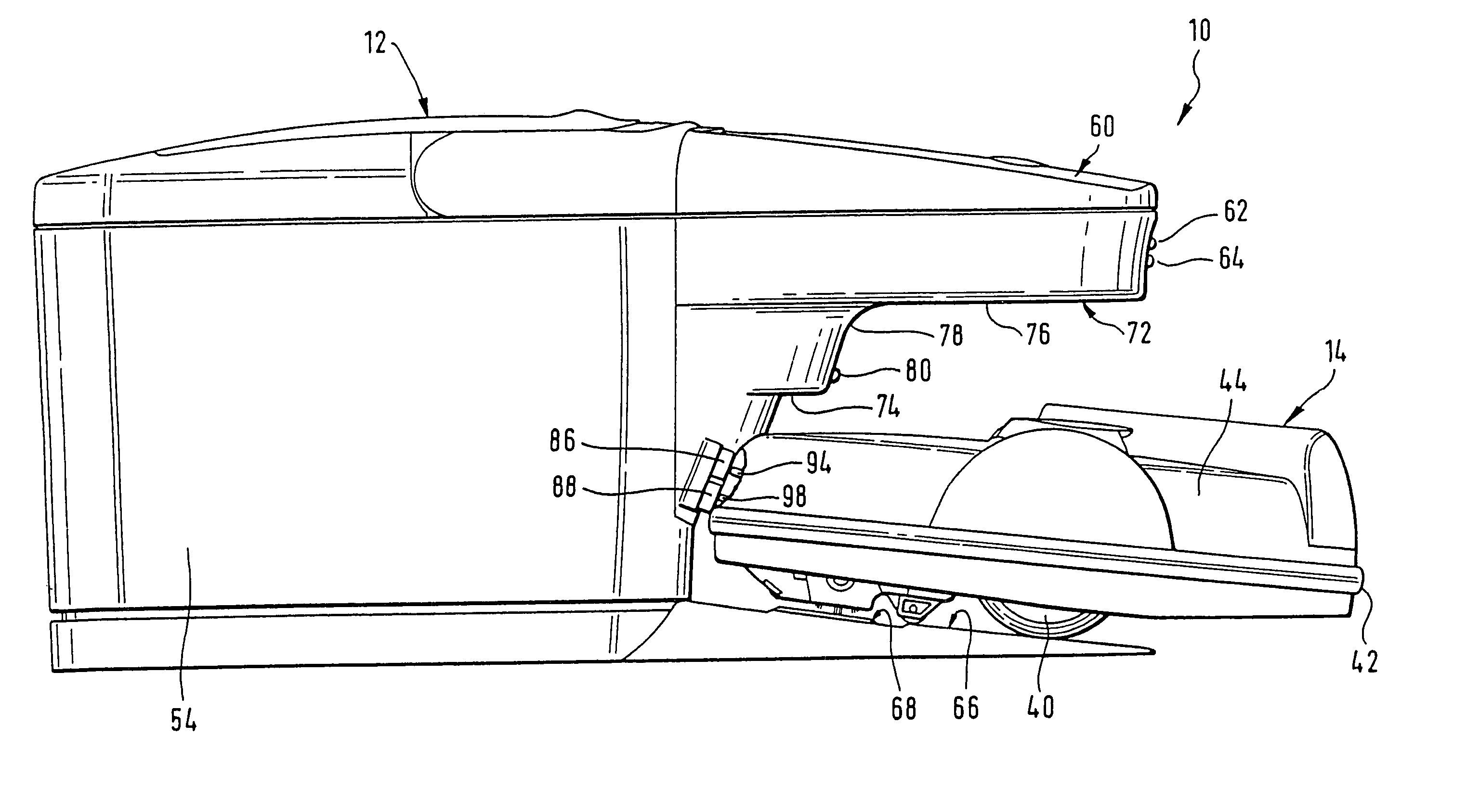
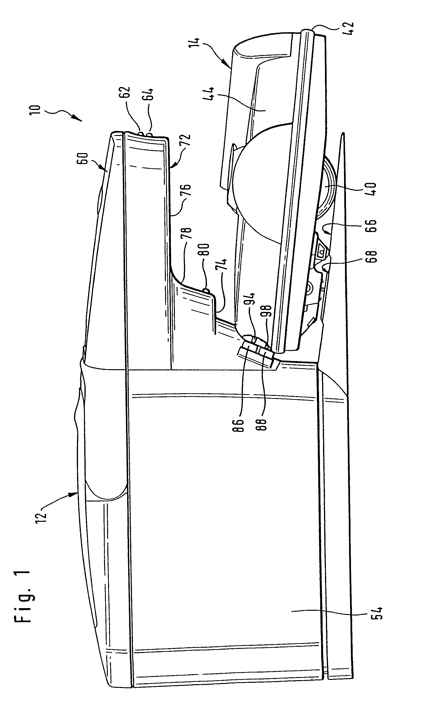
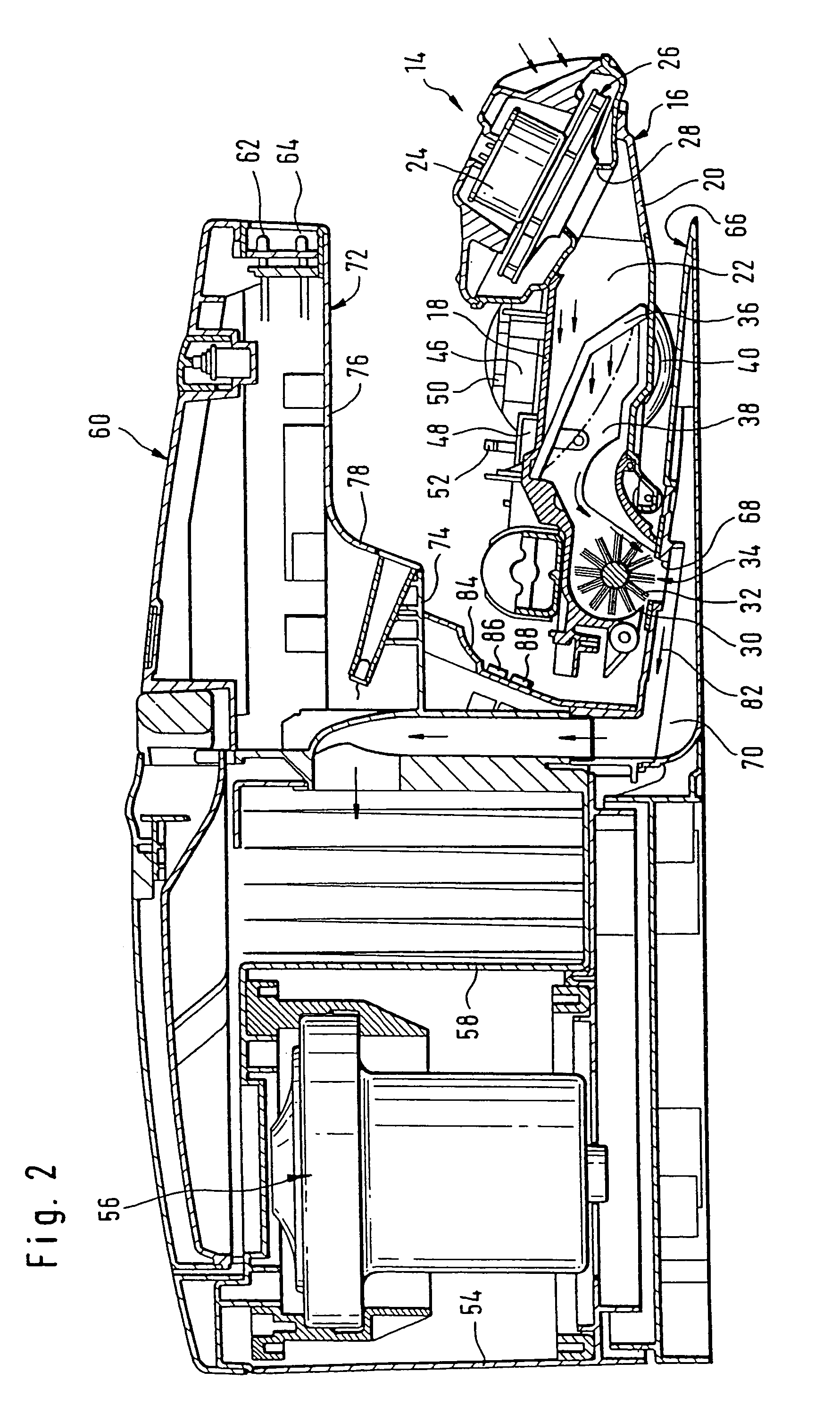
[0039]The drawings show a floor treatment system according to the present invention in the form of a floor cleaning system, which is designated as a whole by the reference numeral 10 and comprises a central charging station 12 and a self-propelled and self-steering floor treatment unit in the form of a mobile suction device 14.

[0040]The suction device 14 is formed as a mobile cleaning robot and has a housing 16 with a top wall 18 and a bottom ...


PUM


Abstract

The invention relates to a floor treatment system with a self-propelled and self-steering floor treatment unit, which comprises an electrically driven floor treatment assembly and also a rechargeable power supply unit, and with a central charging station for recharging the power supply unit, the floor treatment unit being capable of being electrically connected to the charging station by means of respective electrical connecting elements disposed on the charging station and the floor treatment unit. In order to develop the floor treatment system in such a way that improved electrical coupling of the respective connecting elements is made possible, it is proposed according to the invention that at least one of the respective connecting elements is spring-mounted.

Description

[0001]This application is a continuation of international application number PCT / EP 03 / 06224 filed on Jun. 13, 2003, and claims the benefit of German patent application number 102 31 388.1 filed on Jul. 8, 2002.[0002]The present disclosure relates to the subject matter disclosed in international application number PCT / EP 03 / 06224 of Jun. 13, 2003 and German application number 102 31 388.1 of Jul. 8, 2002, which are incorporated herein by reference in their entirety and for all purposes.BACKGROUND OF THE INVENTION[0003]The invention relates to a floor treatment system with a self-propelled and self-steering floor treatment unit.[0004]Self-propelled and self-steering floor treatment units can be used for treating, in particular cleaning, a floor surface without the floor treatment unit having to be moved across the floor surface by an operator. Rather, the floor treatment unit is configured in such a way that it automatically travels across the floor surface and treats it. If it meets...

Claims


Application Information

Patent Timeline
Patent Type & Authority Patents(United States)
IPC IPC(8): A47L9/28A47L9/00A47L9/10H01R13/24
CPCA47L9/009A47L9/106A47L9/2805A47L9/2842A47L9/2852A47L9/2873A47L9/2884H01R13/24A47L9/2857A47L2201/024A47L2201/022
Inventor KEPPLER, JOACHIMMATH, JOCHENSKOUMAL, ROGER
Owner ALFRED KARCHER GMBH & CO KG
Why Eureka
Try Eureka