Method of controlling implant dosage and pressure compensation factor in-situ

a technology of pressure compensation factor and dosage, which is applied in the field of controlling the dosage of implants and the pressure compensation factor in situ, can solve the problems of high accuracy of the pressure compensation factor obtained from the degree of vacuum inside an ion implant station will deteriorate with long-term operation, and the degree of vacuum in the high vacuum chamber of the ion implant station will be proportional to the length of application time. , to achieve the effect of increasing the accuracy of the implan

Active Publication Date: 2006-06-06
PROMOS TECH INC
View PDF11 Cites 4 Cited by
  • Summary
  • Abstract
  • Description
  • Claims
  • Application Information

AI Technical Summary

Benefits of technology

[0008]Accordingly, at least one objective of the present invention is to provide a method of controlling the implant dosage effected by an ion implant station so that the accuracy of the implant is increased despite a drop in the degree of vacuum inside the ion implant station.
[0009]At least a second objective of the present invention is to provide a method of controlling the pressure compensation factor inside an ion implant station in-situ so that the problem of obtaining an inaccurate pressure compensation factor and providing an inaccurate implant dosage is avoided.
[0013]In the present invention, the partial pressure of various residual gases inside the ion implant station and the charge exchange reaction between the residual gases and the ion beam are taken into consideration. Therefore, a highly accurate control of the ion implant dosage can be achieved.

Problems solved by technology

In general, the degree of vacuum inside an ion implant station will deteriorate in proportion to the length of application time.
The reason is that the absorbability of the cooling pump for withdrawing air from a high vacuum chamber of the ion implant station will deteriorate with long-term operation.
In other words, if a portion of the ions is neutralized to atoms as a result of a charge exchange reaction between the residual gases and the ion beam, the current meter inside the ion implant station will not account for the neutralization.
Therefore, the pressure compensation factor obtained from an ion implant station will be highly inaccurate when the degree of vacuum inside the processing chamber drops or there are variations in other factors.
As a result, the ion implant dosage cannot be controlled accurately.

Method used


Image

  • Method of controlling implant dosage and pressure compensation factor in-situ
  • Method of controlling implant dosage and pressure compensation factor in-situ
  • Method of controlling implant dosage and pressure compensation factor in-situ

Examples


Embodiment Construction

[0018]Reference will now be made in detail to the present preferred embodiments of the invention, examples of which are illustrated in the accompanying drawings. Wherever possible, the same reference numbers are used in the drawings and the description to refer to the same or like parts.

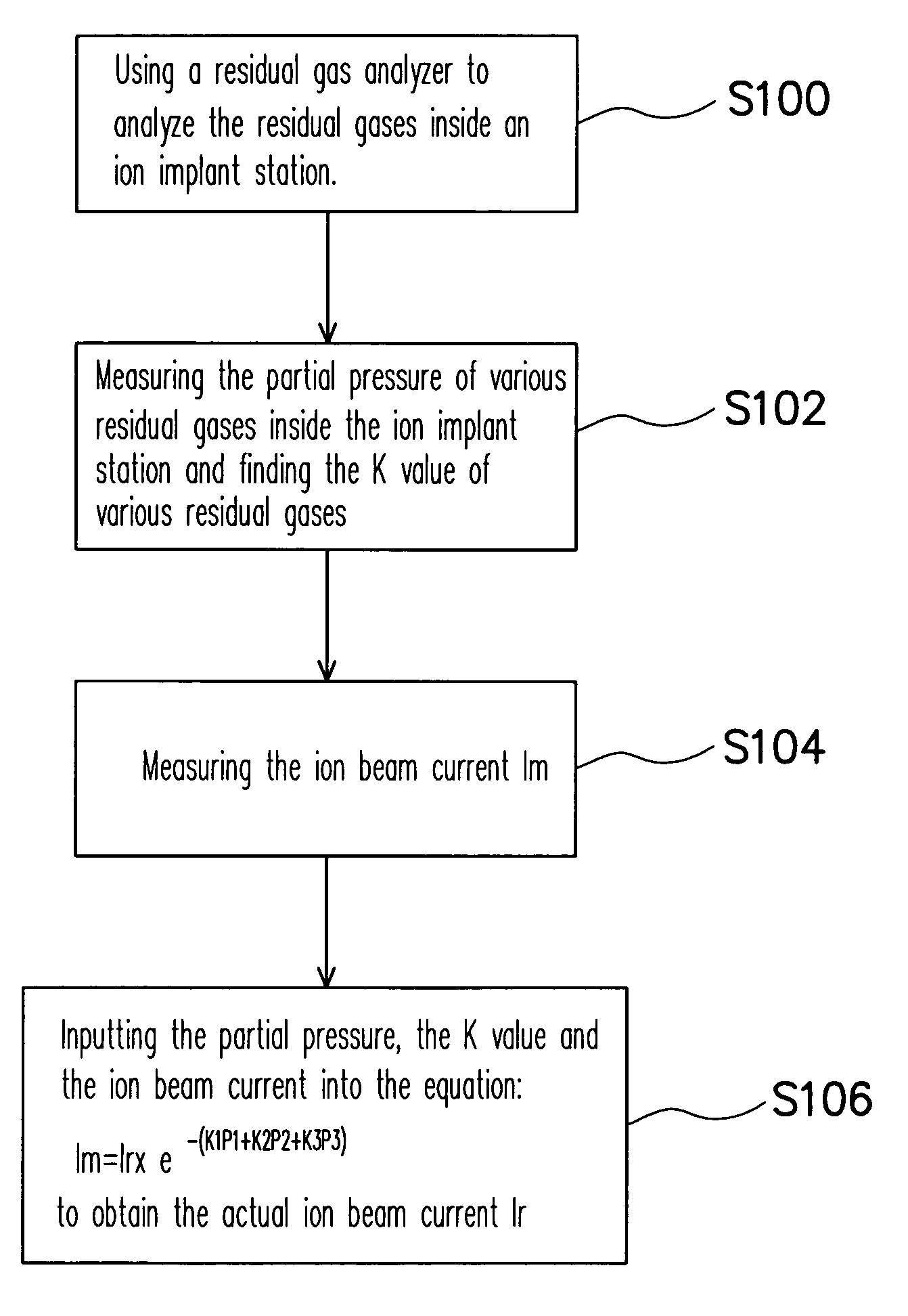
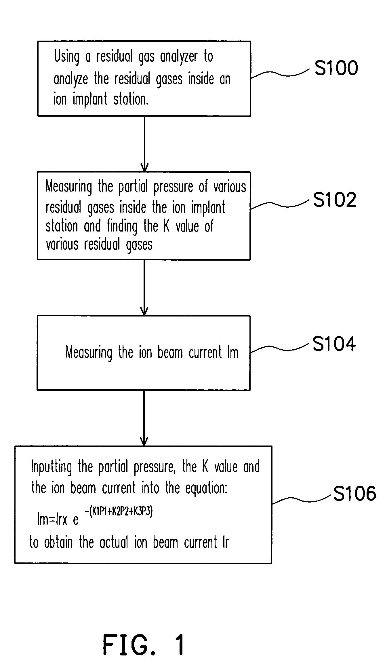
[0019]FIG. 1 is a flow chart showing the steps for accurately controlling the ion implant dosage according to one preferred embodiment of the present invention. First, in step S100, the residual gases inside an ion implant station is analyzed using a residual gas analyzer (RGA). Through the analysis, the type of residual gases inside the ion implant station is obtained. In general, the residual gases are related to the gases previously passed into the ion implant station for carrying out an ion implant process including, for example, argon, carbon dioxide, oxygen, nitrogen, water vapor or hydrogen.

[0020]In step S102, the partial pressure of various residual gases inside the ion implant station is mea...


PUM


Abstract

A method of controlling the implant dosage is provided. First, the residual gases within an ion implant station are analyzed and the partial pressure of each residual gas is measured. Thereafter, the current Im of the ion beam is measured and the real dosage Ir of the ion beam implanted into a wafer is calculated. Since all the residual gases in the ion implant station are considered, the implanting dosage can be accurately controlled.

Description

CROSS-REFERENCE TO RELATED APPLICATION[0001]This application claims the priority benefit of Taiwan application serial no. 92130762, filed on Nov. 4, 2003.BACKGROUND OF THE INVENTION[0002]1. Field of the Invention[0003]The present invention relates to a method of controlling the implant dosage and the pressure compensation factor in situ. More particularly, the present invention relates a method of controlling the in-situ pressure compensation factor through a residual gas analyzer (RGA) so that the concentration of ions implanted into a wafer can be accurately controlled.[0004]2. Description of the Related Art[0005]Ion implantation is commonly adopted technique for implanting dopants into a wafer or specified regions of the wafer in the process of fabricating semiconductor devices. With the reduction in the size of semiconductor devices and an increase in the level of integration, the amount of dopants implanted into designated areas of the wafer must be meticulously controlled. One...

Claims


Application Information

Patent Timeline
Patent Type & Authority Patents(United States)
IPC IPC(8): G21K5/10H01J37/08H01J37/317H01L21/265
CPCH01J37/3171H01J2237/004H01J2237/31705H01J2237/31703H01J2237/18
Inventor HSU, HENG-KAICHEN, YU-CHI
Owner PROMOS TECH INC
Why Eureka
Try Eureka