Wireless LAN with distributed access points for space management

a distributed access point and wireless technology, applied in the field of wireless local area networks, can solve the problems of limited performance improvement, difficult frequency management task, and crowded wireless spectrum, and achieve the effect of aggressive space management and location based services

Inactive Publication Date: 2006-06-06
CISCO TECH INC
View PDF12 Cites 101 Cited by
  • Summary
  • Abstract
  • Description
  • Claims
  • Application Information

AI Technical Summary

Benefits of technology

[0006]Using an arrangement such as this in a dense network where the RF node density is greater than the density of a ne

Problems solved by technology

With the increase in wireless traffic, the wireless spectrum has become increasingly crowded, and the task of frequency management becomes more difficult.
Unfortunately, a typical deployment uses only omnidirectional antennas and protocol methods to manage a network, which have limitations that permit only limited improvements in performance.
However, such packages are

Method used


Image

  • Wireless LAN with distributed access points for space management
  • Wireless LAN with distributed access points for space management
  • Wireless LAN with distributed access points for space management

Examples


Embodiment Construction

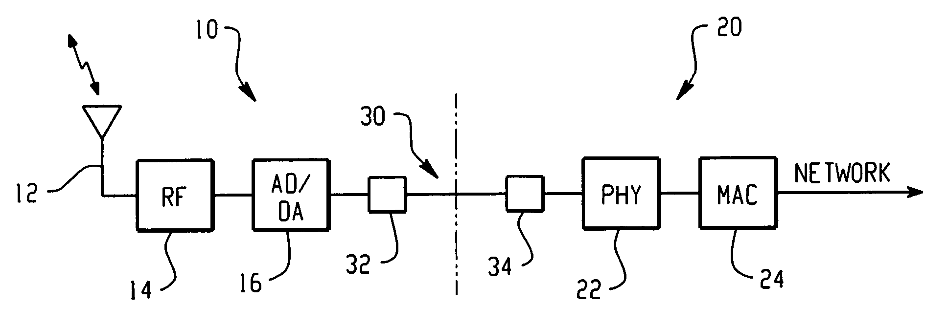
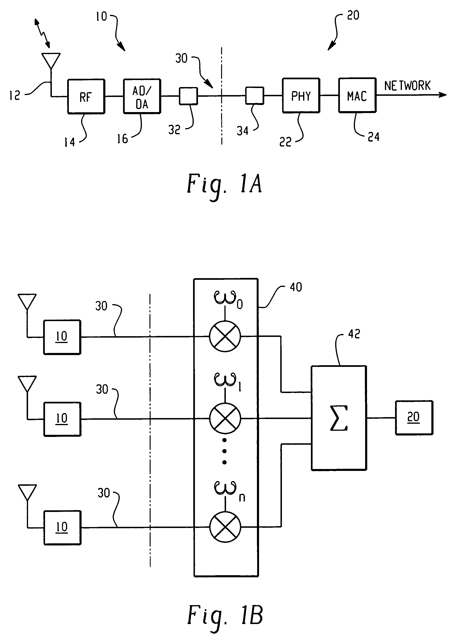
[0010]In the present invention, a wireless LAN is contemplated in which the function of the access points are partitioned, with the radio components distributed in space over a coverage area, and implemented in such a way as to form an adaptive directional antenna array. As shown in FIGS. 1A and 1B, the present directional antenna system includes a plurality of RF nodes 10 that cooperate with a separate and distinct network interface assembly 20. As shown in FIG. 1A, each RF node 10 can cooperate with a single network interface 20. Also, as shown in FIG. 1B, a number of RF nodes 10 can all be configured to cooperate with a single network interface 20. In a single system, any number of RF nodes 10 can cooperate with any respective number of network interfaces 20, as is practicable. In any event, the plurality of RF nodes 10 cooperatively form a directional antenna array for transmitting and receiving wireless signals between a wireless client at a predetermined position in space. It ...


PUM


Abstract

A directional antenna system is disclosed in which a plurality of RF nodes are provided for cooperatively forming a directional antenna array for transmitting and receiving wireless signals between a wireless client at a predetermined position in space. One or more network interface assemblies are provided for exchanging signals between the plurality of RF nodes and a network. Preferably, the plurality of RF nodes are distributed in space with respect to each other and the network interface assembly. The network interface includes a beamformer for applying a plurality of antenna weighting factors to the respective RF nodes, for introducing phase differences in the respective transmitted and received wireless signals that produce a directional steering vector for the wireless signals. In one embodiment of the invention, a processing arrangement is provided for deriving an array manifold, which includes a respective plurality of antenna weighting factors corresponding respectively to distances between each of the plurality of RF nodes, for producing the directional steering vector for the wireless signals. In another embodiment of the invention, a subspace beamforming arrangement is provided for building a covariance matrix from sampled values of a wireless client signal at each RF node, and deriving dominant eigenvectors corresponding to each RF node. The dominant eigenvectors are used as the respective antenna weighting factors for producing the directional steering vectors for the wireless signals.

Description

CROSS REFERENCE TO RELATED APPLICATIONS[0001]This application is related to U.S. patent application Ser. No. 09 / 949,697, filed: Sep. 10, 2001, and assigned to Cisco Technology. Inc., the assignee of this application.BACKGROUND OF THE INVENTION[0002]The present invention is directed to the field of wireless local area networks, particularly those of the type that employ an adaptive directional antenna array for space management. With the increase in wireless traffic, the wireless spectrum has become increasingly crowded, and the task of frequency management becomes more difficult. Unfortunately, a typical deployment uses only omnidirectional antennas and protocol methods to manage a network, which have limitations that permit only limited improvements in performance. Thus, management of space is becoming increasingly important, and promises to improve network capacity, scalability, and quality of service (QoS) performance, and reduce deployment complexity.[0003]Space management can b...

Claims


Application Information

Patent Timeline
IPC IPC(8): H01Q3/26H04B7/04H04L12/28H04W84/12H04W88/02H04W88/08
CPCH01Q3/30H04B7/0408H04W88/08H04W88/02H04W84/12
Inventor LEWIS, MICHAEL E.
Owner CISCO TECH INC
Why Eureka
Try Eureka