Common optical-path testing of high-numerical-aperture wavefronts

a technology of optical path and wavefront, which is applied in the measurement of optical radiation, instruments, measurement devices, etc., can solve the problems of difficult construction and maintenance of high-numerical aperture point reference sources under practical manufacturing and test conditions, difficult wavefront measurements, and difficulty in high-numerical aperture point reference sources, etc., to achieve high degree of polarization and high polarization purity

Active Publication Date: 2006-06-06
ONTO INNOVATION INC
View PDF18 Cites 24 Cited by
  • Summary
  • Abstract
  • Description
  • Claims
  • Application Information

AI Technical Summary

Benefits of technology

[0022]Thus, a benefit of the invention is that it provides a means for measuring a converging wavefront, with path-length-equivalent accuracy of a fraction of wavelength, without the use of a point reference source, as required for calibration of prior-art systems. The orthogonally polarized test and reference beams are produced in a common-path configuration without restriction on the numerical aperture or the wavelength of the input light. The beams are combined in an interferometer with a geometry that maintains their common path through the entire system and allows the simultaneous detection of interferograms on a single detector or a plurality of adjacent detectors. The ratio of power between the test and reference wavefronts may be changed without significant power loss while maintaining high polarization purity in each beam. The invention also provides a high degree of polarization of the test and reference wavefronts independently of the input polarization state and for a large range of wavelengths of the input wavefront.

Problems solved by technology

The trend towards high-numerical-aperture laser systems for high-density storage makes wavefront measurements particularly difficult.
Such a high-numerical-aperture point reference source is difficult to construct and maintain in proper alignment under practical manufacturing and test conditions.
Early common-path designs produced only a single optical interference pattern, which made it difficult to obtain quantitative information about the wavefront under test.
Providing more than one value of phase shift between the object beam (also referred to as the test beam) and the reference beam has proven to be difficult in a common-path design.
Yet, they are restricted to low-numerical-aperture beams because of the limited feature size of the phase-plate.
Also, the temporal nature of phase-shifting techniques requires a high degree of mechanical stability of the pinhole and the interferometer with respect to the test beam during the entire acquisition time (typically, 3 to 7 video frames), thus rendering the technique particularly sensitive to vibrations.

Method used


Image

  • Common optical-path testing of high-numerical-aperture wavefronts
  • Common optical-path testing of high-numerical-aperture wavefronts
  • Common optical-path testing of high-numerical-aperture wavefronts

Examples


Embodiment Construction

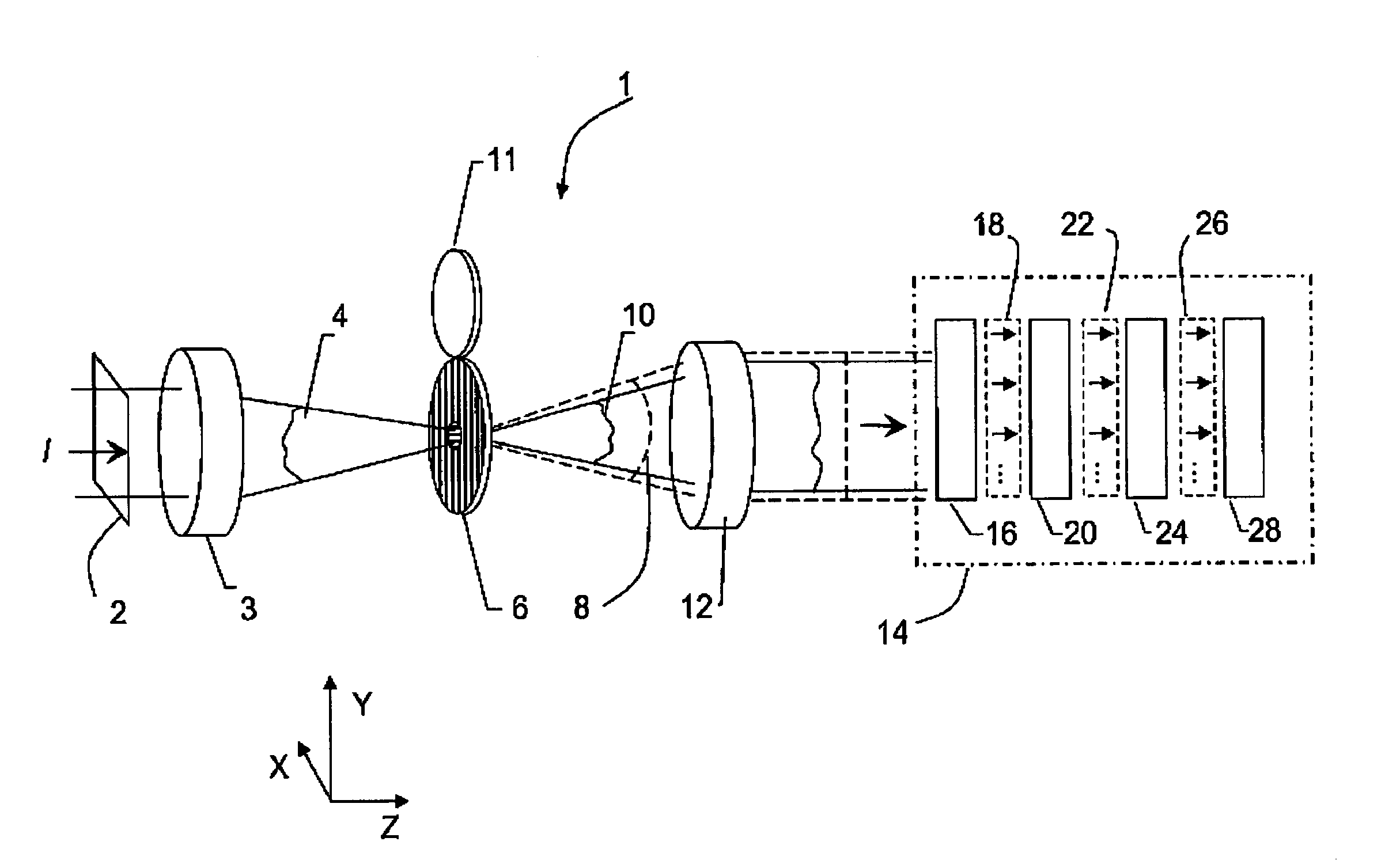
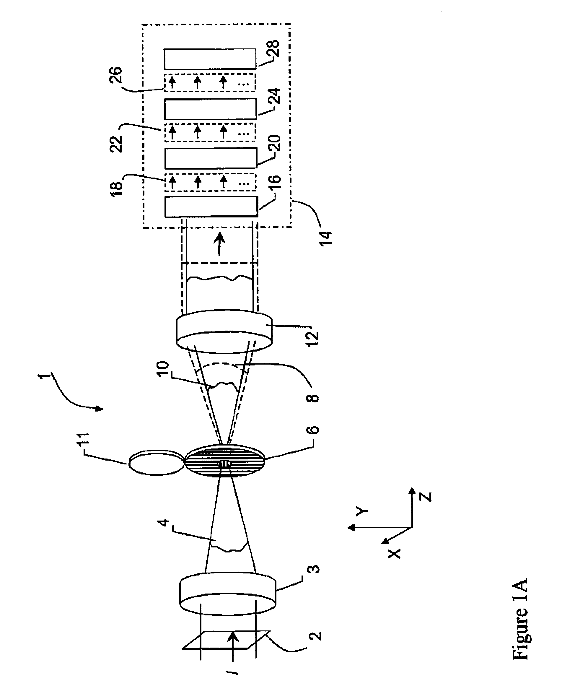
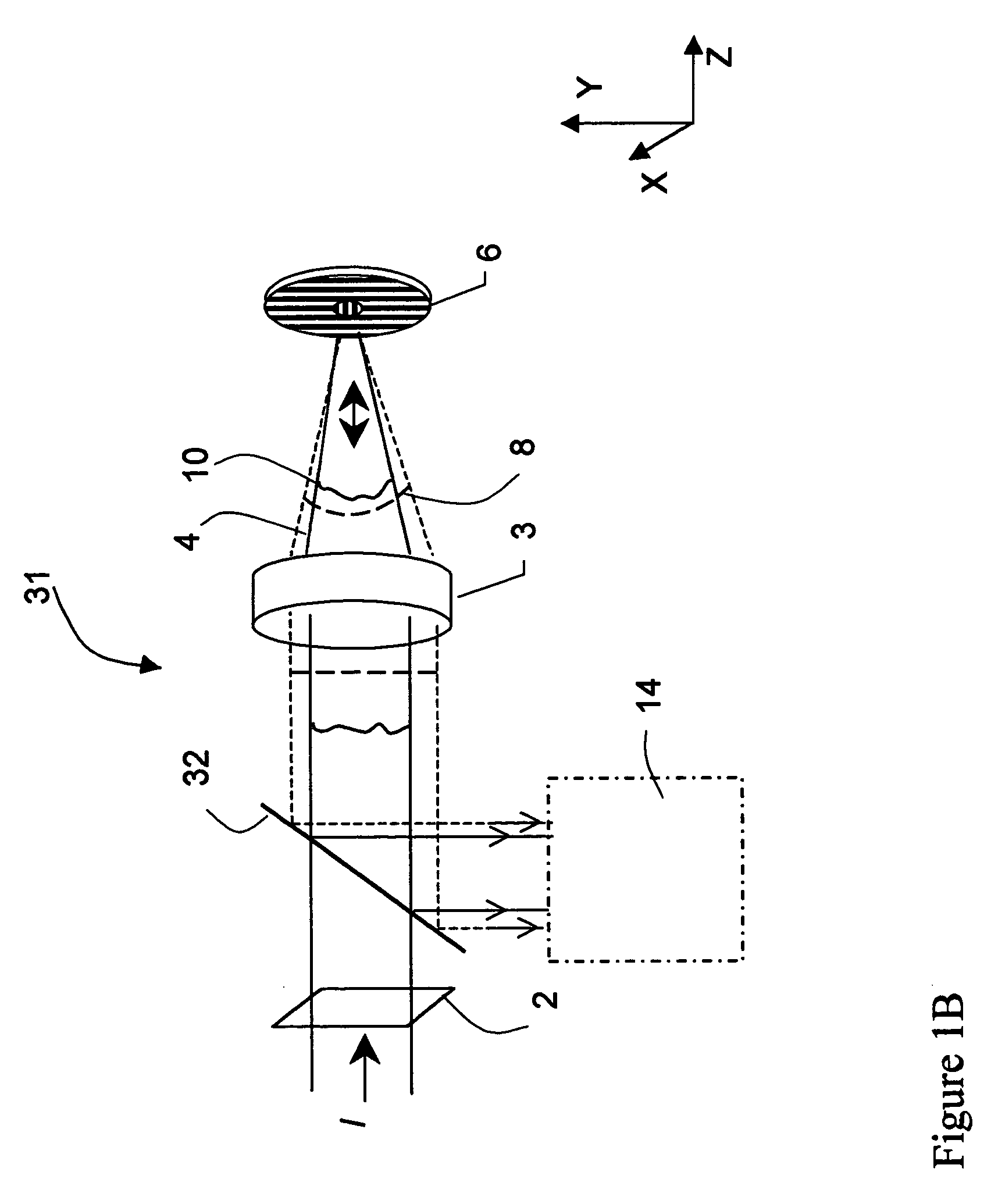
[0037]In general, the invention lies in the combination of an interferometer with a polarizing PDP, as described, wherein common-path test and reference wavefronts are produced. The wavefronts are collimated, phase shifted and interfered, and the resulting interferograms are imaged on a detector. The interference patterns are then processed using any number of algorithms designed to calculate optical difference and determine the input wavefront.

[0038]The invention is particularly suited for measuring high-numerical-aperture converging beams. Such a convergent beam is first transformed by passing the light through a specially made polarization plate that produces a high-quality spherical reference wave in common path with a replica of the original test wavefront, which are polarized in mutually orthogonal directions. A variety of methods can then be used to impart a phase shift between the reference and test beams and effect quantitative interferometric measurements. For example, in ...


PUM


Abstract

A polarizing point-diffraction plate is used to produce common-path test and reference wavefronts with mutually orthogonal polarizations from an input wavefront. The common-path test and reference wavefronts are collimated, phase shifted and interfered, and the resulting interferograms are imaged on a detector. The interference patterns are then processed using conventional algorithms to characterize the input light wavefront.

Description

BACKGROUND OF THE INVENTION[0001]1. Field of the Invention[0002]The present invention relates to measurement of electromagnetic wavefronts. More particularly, the invention pertains to quantitative, instantaneous measurement of strongly converging optical wavefronts.[0003]2. Description of the Related Art[0004]Wavefront measurements are important in the manufacture of many optical components, including optical data-storage laser heads. The trend towards high-numerical-aperture laser systems for high-density storage makes wavefront measurements particularly difficult.[0005]A conventional measurement of the wavefront quality of a light beam may employ spatial filtering of a small portion of the source light to produce a spherical reference wave that is subsequently combined with the original wavefront to produce an interferogram. As is well understood in the art, the intensity pattern generated by the interference yields fringes of constant phase difference that can be analyzed to eva...

Claims


Application Information

Patent Timeline
Patent Type & Authority Patents(United States)
IPC IPC(8): G01B9/02G01J9/02
CPCG01J9/02G01B9/02057G01B9/02097G01B9/02024G01B9/02023G01B9/02038G01B9/02081G01B9/02022G01B2290/30G01B2290/70
Inventor MILLERD, JAMES E.BROCK, NEAL J.HAYES, JOHN B.WYANT, JAMES C.
Owner ONTO INNOVATION INC
Why Eureka
Try Eureka