Coatable polarizer and liquid crystal display device having the same

a liquid crystal display device and polarizer technology, applied in the field of polarizers, can solve the problems of increasing manufacturing costs, inability to precisely align guests along the host, and long process time, and achieve the effect of low manufacturing costs and good transmittance and polarization degr

Active Publication Date: 2015-12-17
LG DISPLAY CO LTD
View PDF2 Cites 16 Cited by
  • Summary
  • Abstract
  • Description
  • Claims
  • Application Information

AI Technical Summary

Benefits of technology

[0016]Therefore, an object of the present invention is to provide a coatable polarizer which incurs low manufacturing cost and having good transmittance and polarization degree, and a liquid crystal display device having the same.

Problems solved by technology

However, when the polarizer is manufactured through the related art method as described above, the polarizer becomes relatively thick, leading to shortcomings of poor heat resistance and moisture resistance of the manufactured polarizer, and in particular, since the orientation process (or stretching process) and the dye process are performed on the PVA polarizer, a process time is lengthened and manufacturing cost increases.
However, the host-guest type polarizer has the following problems.
However, in the related art polarizer, since the several types of guests are mixed to the host, it is not easy to mix the hosts and the guests in an appropriate ratio, and thus, it is not possible to precisely align the guests along the host.
In this case, however, since the various types of guests are not sufficiently mixed, a polarization degree is not uniformly maintained in the entire region of visible rays, reducing the polarization degree.

Method used


Image

  • Coatable polarizer and liquid crystal display device having the same
  • Coatable polarizer and liquid crystal display device having the same
  • Coatable polarizer and liquid crystal display device having the same

Examples


Embodiment Construction

[0029]Description will now be given in detail of the exemplary embodiments, with reference to the accompanying drawings. For the sake of brief description with reference to the drawings, the same or equivalent components will be provided with the same reference numbers, and description thereof will not be repeated.

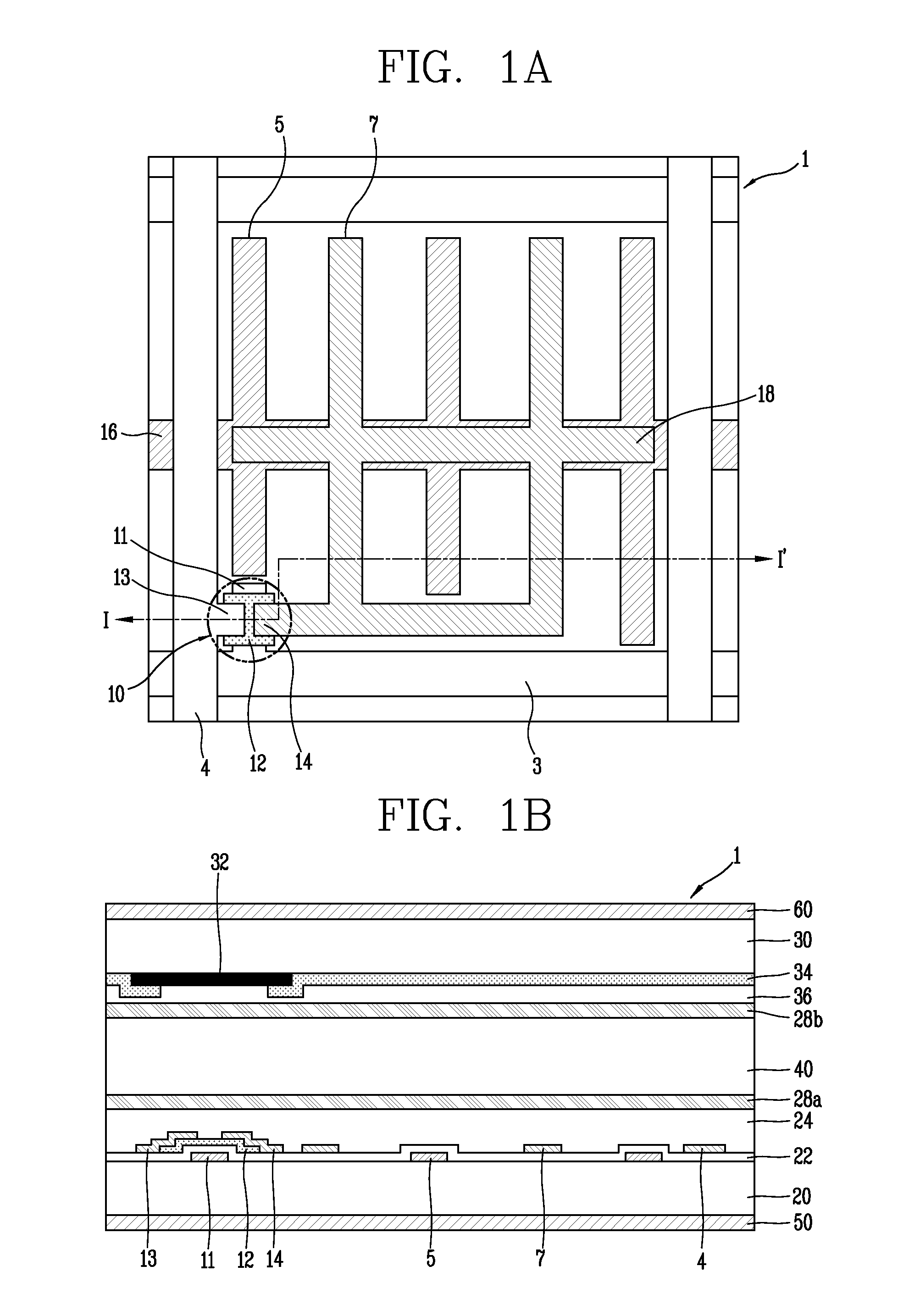
[0030]FIG. 1A is a plan view illustrating a structure of a liquid crystal display (LCD) device according to an embodiment of the present disclosure, and FIG. 1B is a cross-sectional view taken along line I-I′ of FIG. 1A. Here, the LCD device illustrated in FIGS. 1A and 1B is an in-plane switching (IPS) mode LCD device, but the present disclosure is not limited thereto and may also be applied to various modes of LCD devices such as a twisted nematic (TN) mode LCD device, a vertical alignment (VA) mode LCD device, a fringe field switching (FFS) mode LCD device.

[0031]As illustrated in FIG. 1A, a pixel of a liquid crystal panel 1 is defined by a gate line 3 and a data line 4 d...


PUM

PropertyMeasurementUnit
thicknessaaaaaaaaaa
thicknessaaaaaaaaaa
transmittanceaaaaaaaaaa

Abstract

There is provided a coatable polarizer which incurs low manufacturing cost and has an excellent polarization degree and transmittance. A plurality of polarization layers are formed on the coatable polarizer, and each of the polarization layers include about 5 to 7 wt % of dichroic dyes, whereby a light component parallel to an alignment direction of a dichroic dye, among light having a wavelength corresponding to a color, is absorbed to have polarization characteristics.

Description

CROSS-REFERENCE TO RELATED APPLICATION[0001]Pursuant to 35 U.S.C. §119(a), this application claims the benefit of earlier filing date and right of priority to Korean Application No. 10-2014-0073713, filed on Jun. 17, 2014, the contents of which is incorporated by reference herein in its entirety.BACKGROUND OF THE INVENTION[0002]1. Field of the Invention[0003]The present disclosure relates to a polarizer and, more particularly, to a coatable polarizer which has a high degree of polarization and transmittance and is low in price and a liquid crystal display having the same.[0004]2. Background of the Invention[0005]In general, a liquid crystal display includes two substrates disposed to face one another at a predetermined space therebetween and a liquid crystal layer injected between the two substrates. Here, liquid crystal has refractive index anisotropy with respect to a shorter axis and a longer axis, making light have a refractive index changing when transmitting through the liquid...

Claims


Application Information

Patent Timeline
Patent Type & Authority Applications(United States)
IPC IPC(8): G02F1/1335G02B5/30
CPCG02F1/133533G02B5/3016G02B5/3041G02B5/305
Inventor KIM, YOUNGWOOKNOH, HYUNJONGPARK, JIWOONG
Owner LG DISPLAY CO LTD
Why Eureka
Try Eureka