Assembly for inflating a tire

a tire and assembly technology, applied in the direction of tyre-inflating valves, tyre measurements, functional valve types, etc., can solve the problems of inhibiting the performance and efficiency of bicycles, and achieve the effect of no efficiency loss

Inactive Publication Date: 2006-06-13
MCKOY FRLYN R
View PDF10 Cites 11 Cited by
  • Summary
  • Abstract
  • Description
  • Claims
  • Application Information

AI Technical Summary

Benefits of technology

[0006]The present invention meets the needs presented above by utilizing a pump that is removably attached to the spoke of a tire and a plate removably mounted on the frame of the bicycle for engaging a pump actuator. Wherein a user may selectively place the plate in contact with the actuator such that the rotation of the tire causes the actuator to eject compressed air. This allows the user to also disengage the plate so that no efficiency is lost when the tire is not being inflated.

Problems solved by technology

Such a device should not be integrated into the wheel assembly or gears of the bicycle as such integration is costly, not easily retrofitted and may inhibit the performance and efficiency of the bicycle.

Method used


Image

  • Assembly for inflating a tire
  • Assembly for inflating a tire
  • Assembly for inflating a tire

Examples


Embodiment Construction

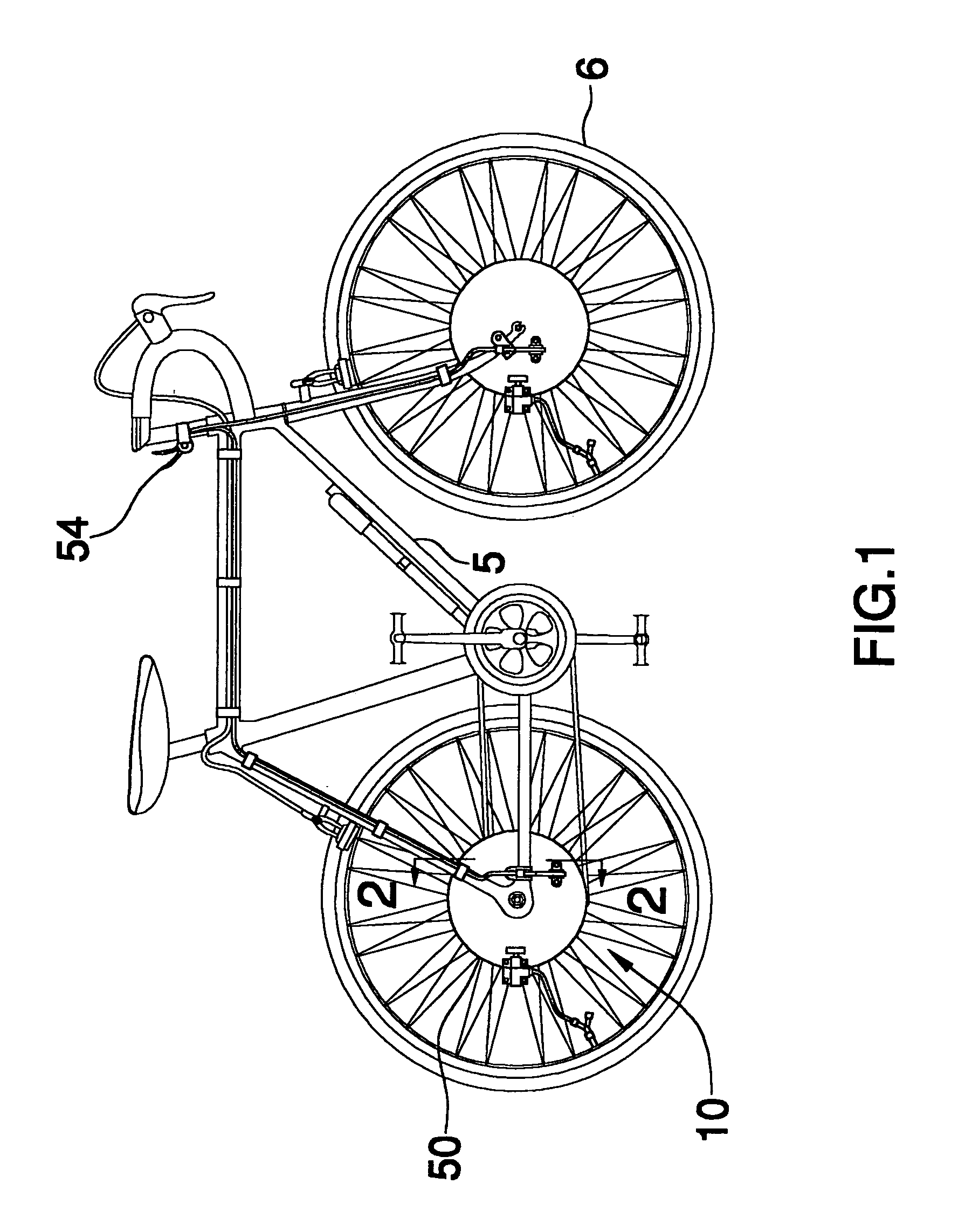
[0017]With reference now to the drawings, and in particular to FIGS. 1 through 6 thereof, a new tire inflating device embodying the principles and concepts of the present invention and generally designated by the reference numeral 10 will be described.

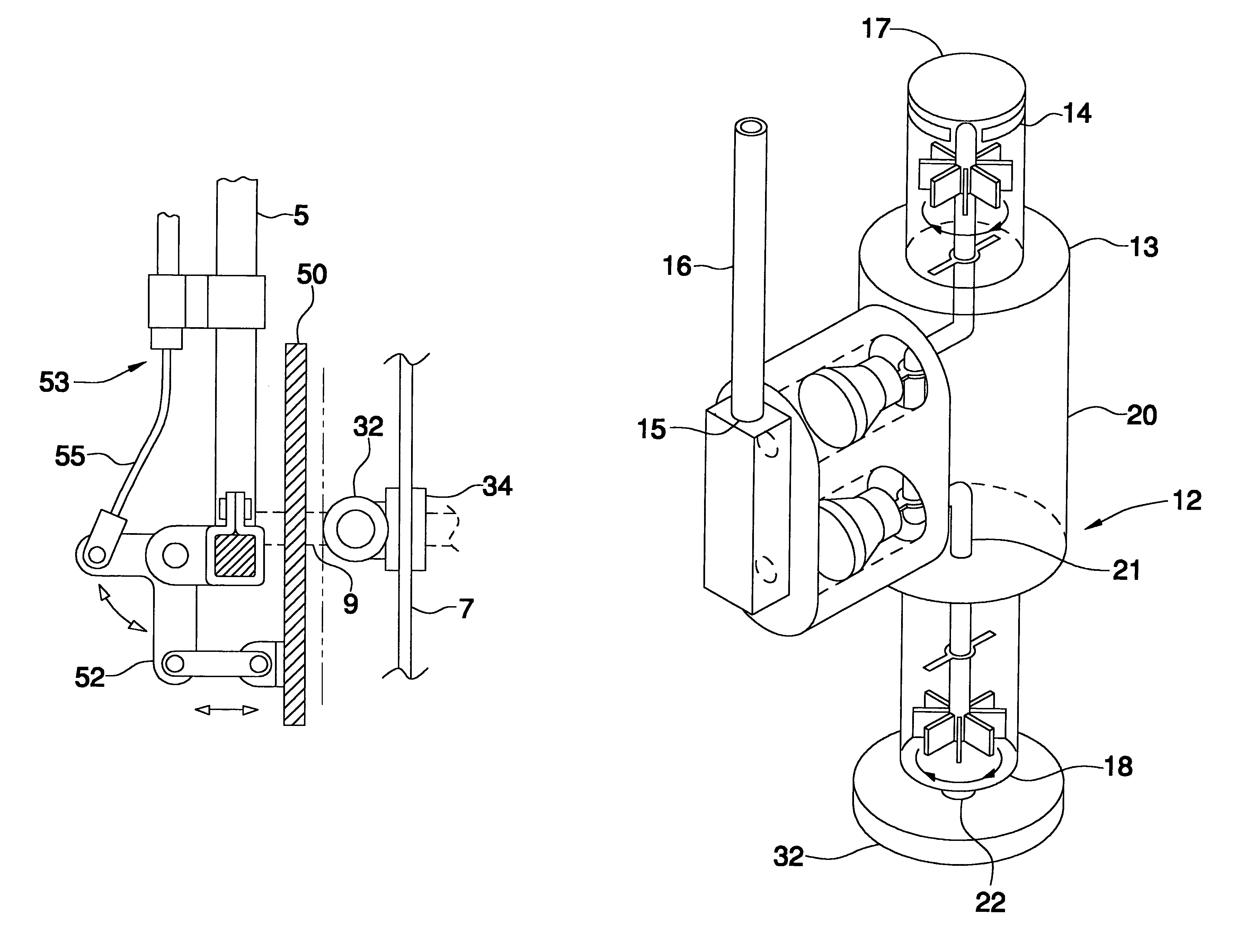
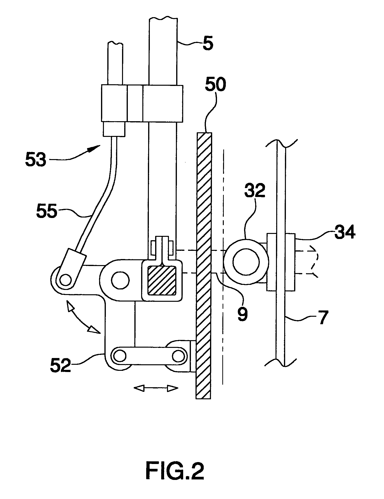
[0018]As best illustrated in FIGS. 1 through 6, the assembly for inflating a tire 10 generally includes a pump assembly 12 that includes a housing 13. The housing 13 has an air inlet 14 and an air outlet 15. A conduit 16 is fluidly coupled to the air outlet 15. The conduit 16 is preferably an elongated tube. The housing 13 has a first end wall 17, a second end wall 18 and a peripheral wall 20 extending between the first 17 and second 18 ends walls. A crankshaft 21 is mounted in the housing 13 and has a free end 22 extending outwardly of the first end wall 17. Preferably two cylinders 23 are positioned in the peripheral wall 20 and extend into an inner surface 24 of the peripheral wall 20 toward an outer surface 25 of the peripheral wal...


PUM


Abstract

An assembly for inflating a tire includes a pump assembly that includes a housing having an air inlet and an air outlet. A conduit is fluidly coupled to the air outlet. The housing has a first end wall, a second end wall and a peripheral wall. A bracket is attached to the housing and is positioned on the peripheral wall for removably securing the housing to a spoke of a tire. The actuator includes a disc rotatably coupled to the pump assembly wherein rotation of the disc actuates the pump assembly. A valve assembly is fluidly couples the conduit to a valve stem of the tire. A plate is removably attached to a frame of a bicycle such that an axle of the tire extends through the plate. The plate is selectively abutted against the disc such that the disc rotates when abutted the plate and rotated around the axle.

Description

BACKGROUND OF THE INVENTION[0001]1. Field of the Invention[0002]The present invention relates to tire inflating devices and more particularly pertains to a new tire inflating device for automatically inflating a bicycle tire while the bicycle is being ridden.[0003]2. Description of the Prior Art[0004]The use of tire inflating devices is known in the prior art. These, generally, having fallen into the category of devices which have been incorporated into the gears or chair of the bicycle. These include U.S. Pat. No. 3,342,177 which is integrated with the wheel assembly of a bicycle, or motorcycle, tire. U.S. Pat. No. 5,626,072 describes a device that is positioned on the chain of bicycle whereby the motion of the chain around the bicycle gears is utilized to actuate the pump.[0005]While these devices fulfill their respective, particular objectives and requirements, the need remains for a device that is more easily retrofitted to an existing bicycle frame for allowing a person to sele...

Claims


Application Information

Patent Timeline
Patent Type & Authority Patents(United States)
IPC IPC(8): B60C23/10
CPCB60C23/12B60C23/129Y10T137/3584
Inventor MCKOY, FRANKLYN R.
Owner MCKOY FRLYN R
Why Eureka
Try Eureka