Check patentability & draft patents in minutes with Patsnap Eureka AI!

Method and apparatus for extending the operating range of a flyforward converter

a flyforward converter and operating range technology, applied in the field of flyforward converters, can solve the problems of restricting the use of the flyforward converter in many practical circuits, limiting the use of the flyforward converter to applications, and the limited range of input voltage applied to the input of the power conversion circui

Active Publication Date: 2006-06-13
POWER INTEGRATIONS INC
View PDF6 Cites 22 Cited by
  • Summary
  • Abstract
  • Description
  • Claims
  • Application Information

AI Technical Summary

Benefits of technology

This technique extends the operating range of flyforward converters to lower input voltages, reducing the stress on power switches and rectification diodes, making them more suitable for applications with varying input conditions.

Problems solved by technology

However, the flyforward configuration suffers from a limitation in its operating characteristic, which restricts its use in many practical circuits.
This typically limits the use of the flyforward converter to applications where the range of input voltage applied to the input of the power conversion circuit is very limited.
This is a severe limitation since many applications having limited input voltage range specifications under normal operating conditions, have short term transient operating conditions where low input voltage must be tolerated with the power converter remaining fully operational.
Although this is only a transient condition in the operation of the power converter, the limitations of the flyforward converter discussed above, make it necessary to rate the voltage of the power switch and output rectifiers to withstand this transient condition.
This limitation can greatly increase the cost of the overall converter, making other converter topologies more attractive for this reason alone.

Method used


Image

  • Method and apparatus for extending the operating range of a flyforward converter
  • Method and apparatus for extending the operating range of a flyforward converter
  • Method and apparatus for extending the operating range of a flyforward converter

Examples


Embodiment Construction

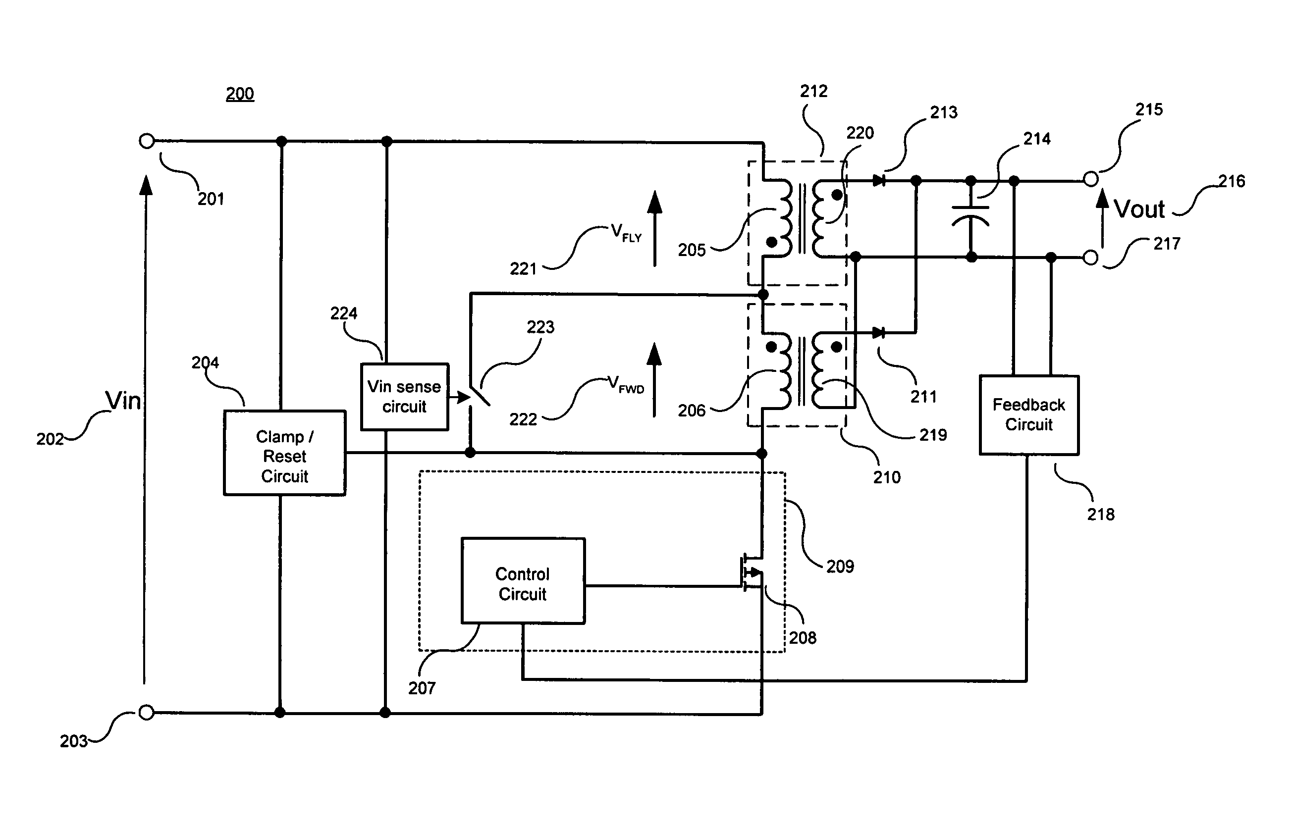
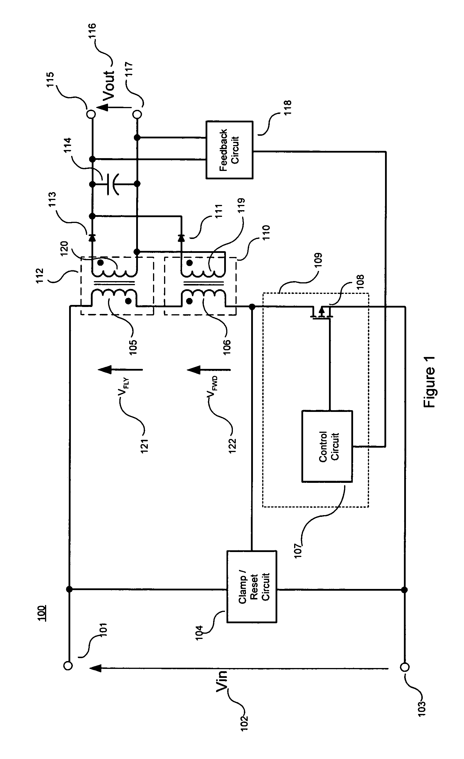
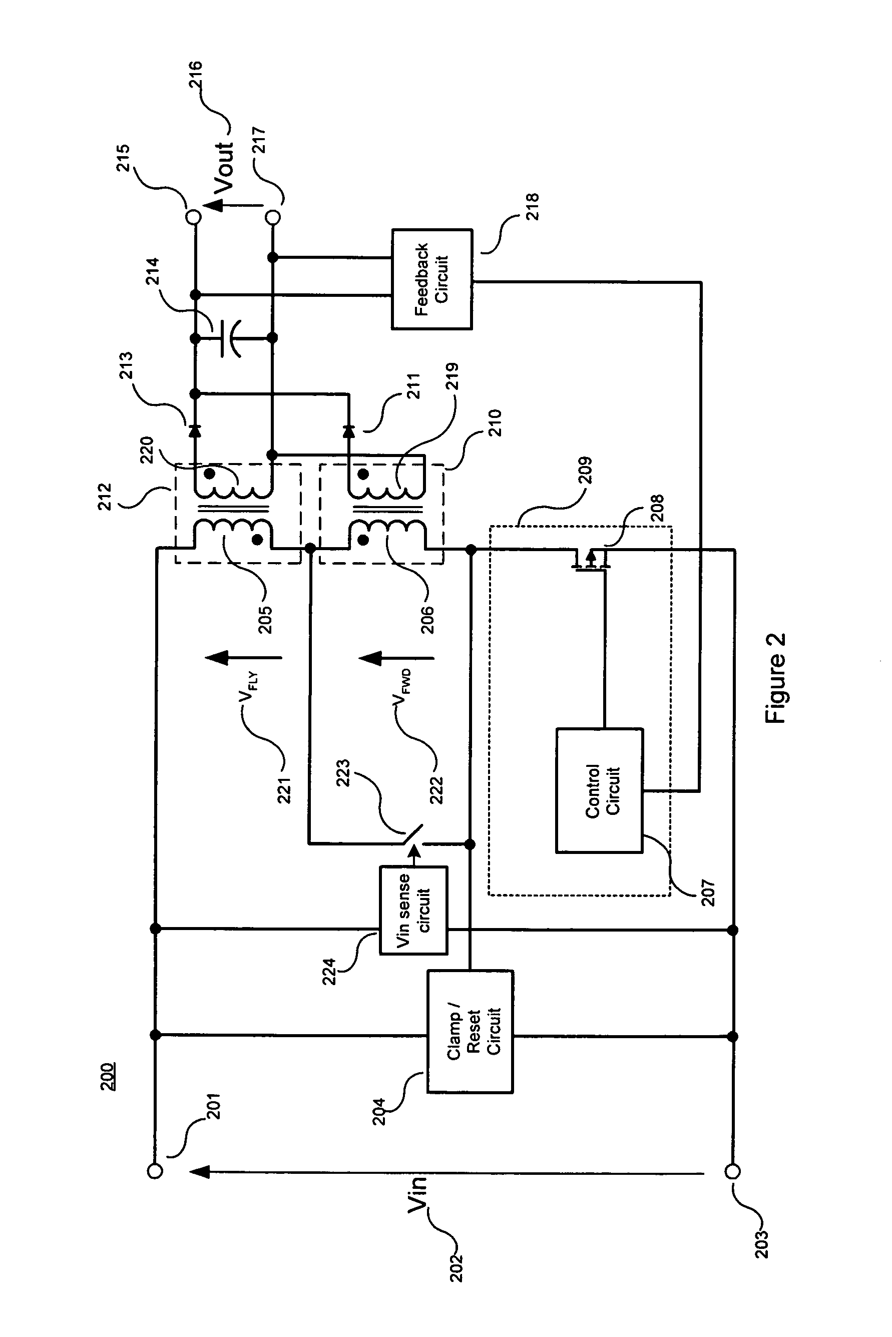
[0022]A novel technique to extend the operating range of a flyforward converter is disclosed. In the following description, numerous specific details are set forth in order to provide a thorough understanding of the present invention. It will be apparent, however, to one having ordinary skill in the art that the specific detail need not be employed to practice the present invention. In other instances, well-known materials or methods have not been described in detail in order to avoid obscuring the present invention.

[0023]In general, a simple and novel technique for extending the operating range of a flyforward converter is provided according to embodiments of the present invention. In various embodiments, either the voltage across the forward energy transfer element input winding is reduced substantially to zero or the voltage across the flyback energy transfer element input winding is increased to substantially equal the power converter input voltage during the on period of a powe...


PUM


Abstract

A technique for extending the operating range of a flyforward converter to low input voltages. In one aspect, power converter includes a positive input supply rail and a negative input supply rail. A power converter input voltage is to be applied between the positive and negative input supply rails. A flyback energy transfer element having a flyback input winding and a forward energy transfer element having a forward input winding are also included. The flyback and forward input windings are coupled between the positive and negative input supply rails. Voltage control circuitry coupled to the forward energy transfer element is also included to reduce a voltage across the forward input winding, substantially to zero, when the power converter input voltage falls below a first threshold value.

Description

BACKGROUND OF THE INVENTION[0001]1. Field of the Invention[0002]The present invention relates generally to power converters and, more specifically, the present invention relates to flyforward power converters.[0003]2. Background Information[0004]Power conversion circuits are typically designed to meet cost and efficiency targets defined at the start of a design. The type of power conversion circuit adopted in a particular design determines the overall system cost and operating performance.[0005]One circuit configuration that provides the advantages of high efficiency and low system cost is a power conversion circuit called a flyforward converter. This circuit configuration effectively combines elements of two commonly used converter configurations, the flyback converter and the forward converter.[0006]The flyforward converter includes individual flyback and forward transformers or energy transfer elements each having an input winding and at least one output winding. One of the advan...

Claims


Application Information

Patent Timeline
Patent Type & Authority Patents(United States)
IPC IPC(8): H02M3/335H02M3/28
CPCH02M3/335H02M3/33569H02M3/33538
Inventor ODELL, ARTHUR B.HESTER, RICHARD L.CUADRA, JASON E.
Owner POWER INTEGRATIONS INC
Features
  • R&D
  • Intellectual Property
  • Life Sciences
  • Materials
  • Tech Scout
  • Unparalleled Data Quality
  • Higher Quality Content
  • 60% Fewer Hallucinations
Learn More