
Method and apparatus for leak detection in low density gas-filled disk drives

a low density, gas-filled disk drive technology, applied in liquid/fluent solid measurement, machines/engines, instruments, etc., can solve the problems of reducing the read/write quality factor, affecting the positioning accuracy of the transducer head, and leaking gas, so as to achieve the effect of simple hardware components and little or no increase in the cost and complexity of the disk driv

Active Publication Date: 2006-06-13
MAXTOR
View PDF20 Cites 30 Cited by
  • Summary
  • Abstract
  • Description
  • Claims
  • Application Information

AI Technical Summary

Benefits of technology

[0011]The invention relates to the detection of leaks in low density gas-filled disk drives. As used herein, a low density gas is a gas having a density that is lower than air. In particular, embodiments of the present invention allow leaks in gas-filled disk drives to be detected using features or components that may be normally included as part of a disk drive. That is, embodiments of the present invention allow for the detection of leaks in gas-filled disk drives without requiring additional hardware components. Accordingly, embodiments of the present invention allow a signal indicating the loss of gas from the interior of a hard drive to be generated, with little or no increase in the cost and complexity of the disk drive in order to provide such a signal. In accordance with other embodiments of the present invention, simple hardware components may be added.
[0016]In accordance with embodiments of the present invention, action may be taken based on a determination that gas has leaked from a disk drive. For example, if a gas leak is detected, a user or administrator of a device incorporating or associated with the disk drive may be notified, so that an attempt to remove data from the disk drive can be made, before total failure of the drive. As a further example, if a loss of gas and replacement of that gas by air is detected, a data recovery mode may be entered in which the rotational velocity of the data storage disks is reduced, thereby reducing the flying height of associated transducer heads, allowing data to be read from the disk drive before failure.

Problems solved by technology

For instance, an improvement in a read / write quality factor may indicate that gas has leaked from the drive without being replaced by air, while a decrease in a read / write quality factor may indicate that gas has leaked and been replaced by air.
As a further example, an improvement in transducer head positioning accuracy may indicate that gas has leaked from the disk drive without being replaced by air, while a degradation of transducer head positioning accuracy may indicate that gas has leaked from the disk drive and been replaced by air.

Method used


Image

  • Method and apparatus for leak detection in low density gas-filled disk drives
  • Method and apparatus for leak detection in low density gas-filled disk drives
  • Method and apparatus for leak detection in low density gas-filled disk drives

Examples


Embodiment Construction

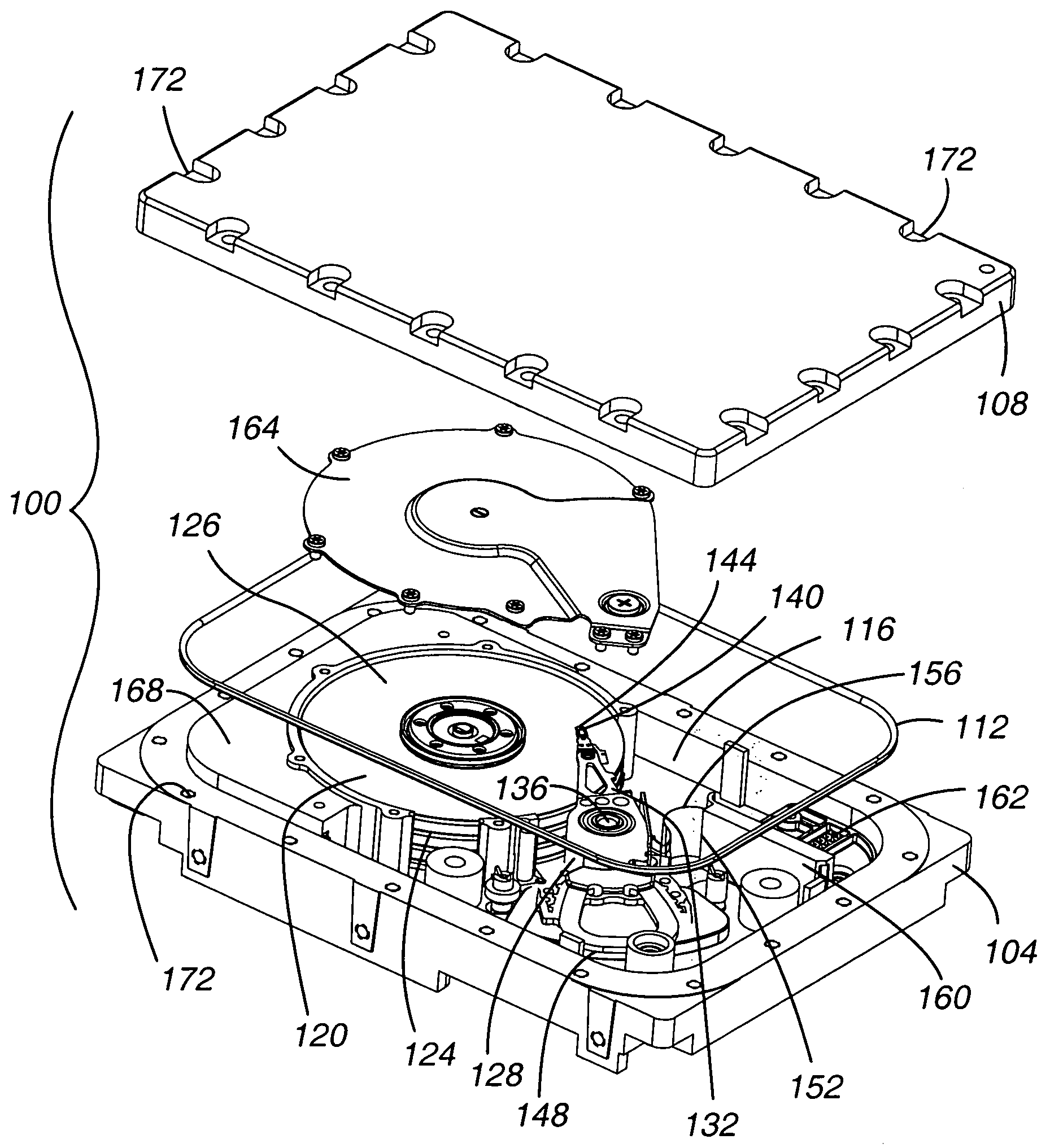
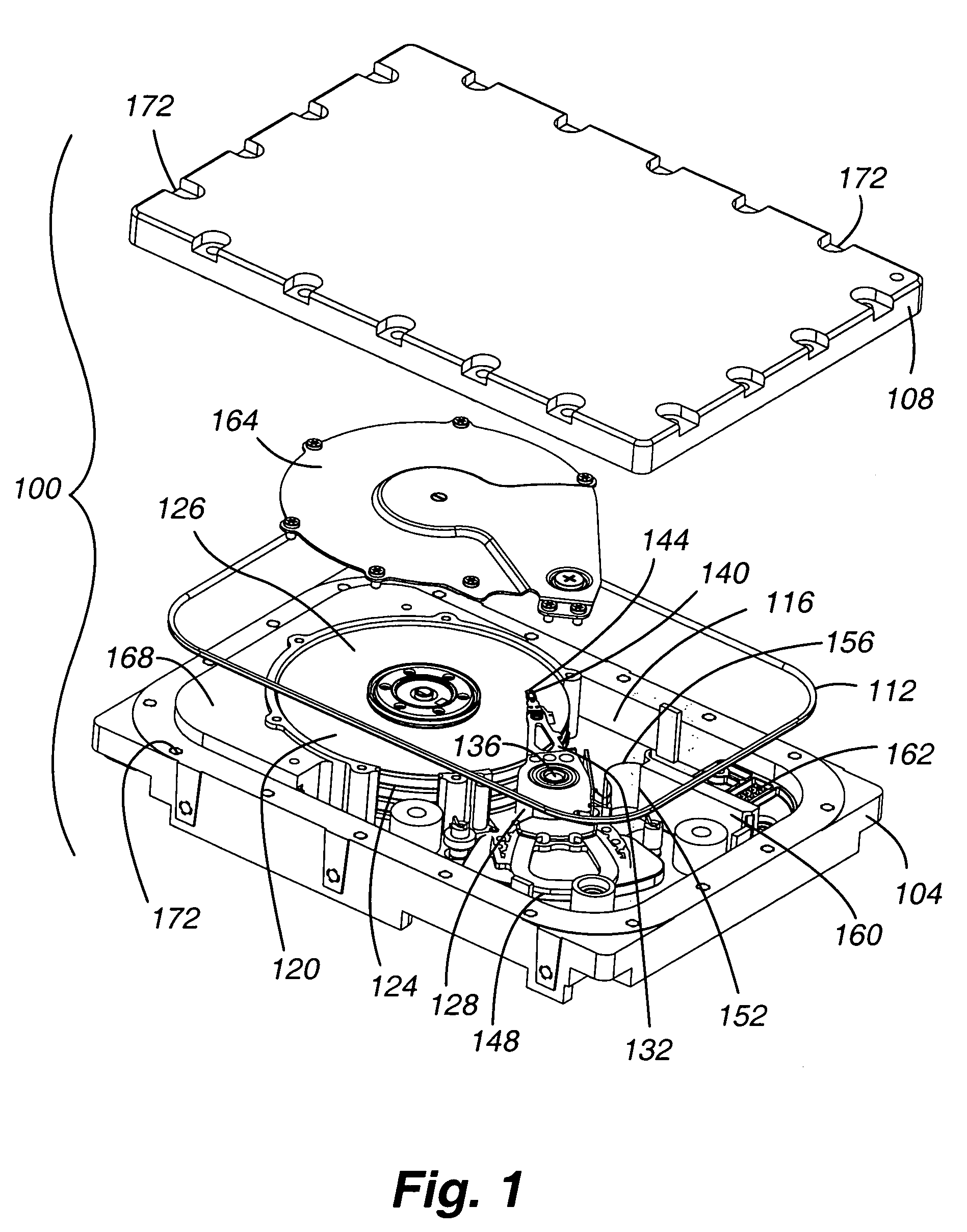
[0030]With reference now to FIG. 1, components of a hard disk drive 100 in accordance with embodiments of the present invention are shown in an exploded view. In general, the hard disk drive 100 includes a base plate 104 and a cover 108. In addition, embodiments of the present invention include a seal 112 to inhibit the leakage of a gas contained in a head disk assembly cavity 116 when the cover 108 is interconnected to the base plate 104. In general, the base plate 104, the cover 108, and the seal 112 comprise the disk drive 100 enclosure.

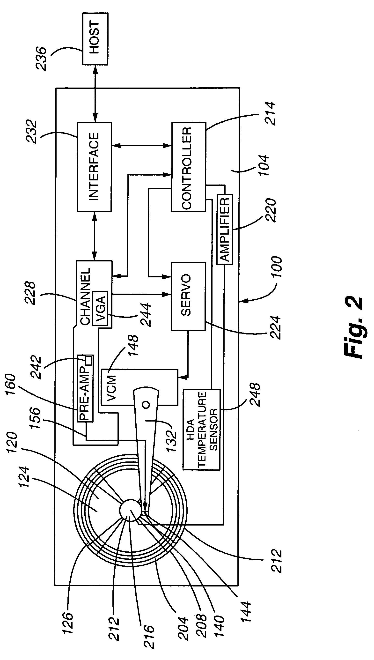
[0031]The hard disk drive 100 additionally includes a disk stack 120 that includes a number of storage disks 124, each having one or two recording surfaces 126. The storage disks 124 of the disk stack 120 are interconnected to the base plate 104 by a spindle bearing 212 (see FIG. 2). A spindle motor 216 (see FIG. 2) may be integral to or associated with the spindle bearing to rotate the disks 124 relative to the base plate 104. In operation, the s...


PUM

PropertyMeasurementUnit
pressureaaaaaaaaaa
pressureaaaaaaaaaa
pressureaaaaaaaaaa

Abstract

The present invention is directed to the detection of gas leaks from a gas-filled disk drive. In accordance with embodiments of the present invention, gas leaks from a disk drive can be detected by monitoring certain disk drive parameters. Furthermore, different types and instances of disk drive parameters may be monitored. No or few additional hardware components are required to be added to a disk drive in connection with implementing embodiments of the present invention.

Description

FIELD OF THE INVENTION[0001]The present invention is related to low density gas-filled disk drives. In particular, the present invention is directed to the detection of leaks in low density gas-filled disk drives.BACKGROUND OF THE INVENTION[0002]Hard disk drives incorporate magnetic storage disks and read / write heads which are capable of reading data from and writing data onto the rotating storage disks. Data is typically stored on each magnetic storage disk in a number of concentric tracks on the disk. The read / write heads, also referred to as read / write transducers or read / write elements, are integrated within a slider. The slider, in turn, is part of an actuator assembly which positions the heads relative to the surface of the storage disks. This may be at a predetermined height above the corresponding storage disk. The actuator assembly is typically controlled by a voice coil motor which acts to position the slider over the desired track. One or more read / write heads may be inte...

Claims


Application Information

Patent Timeline
Patent Type & Authority Patents(United States)
IPC IPC(8): G01F17/00G01N25/72
CPCG11B33/1466
Inventor BURNS, ROBERT STEVENSRIKRISHNA, PADMANABHANFITZPATRICK, JAMESHENRY, JASONDELPAPA, KEN
Owner MAXTOR
Learn More