Connecting device for an antenna

Inactive Publication Date: 2006-06-20
HUANG LIANG PRECISION ENTERPRISE
View PDF1 Cites 23 Cited by
  • Summary
  • Abstract
  • Description
  • Claims
  • Application Information

AI Technical Summary

Benefits of technology

[0007]It is the primary object of the present invention to provide a connecting device for an antenna, which uses an elastic element to prov

Problems solved by technology

This causes a bad or impro

Method used


Image

  • Connecting device for an antenna
  • Connecting device for an antenna
  • Connecting device for an antenna

Examples


Embodiment Construction

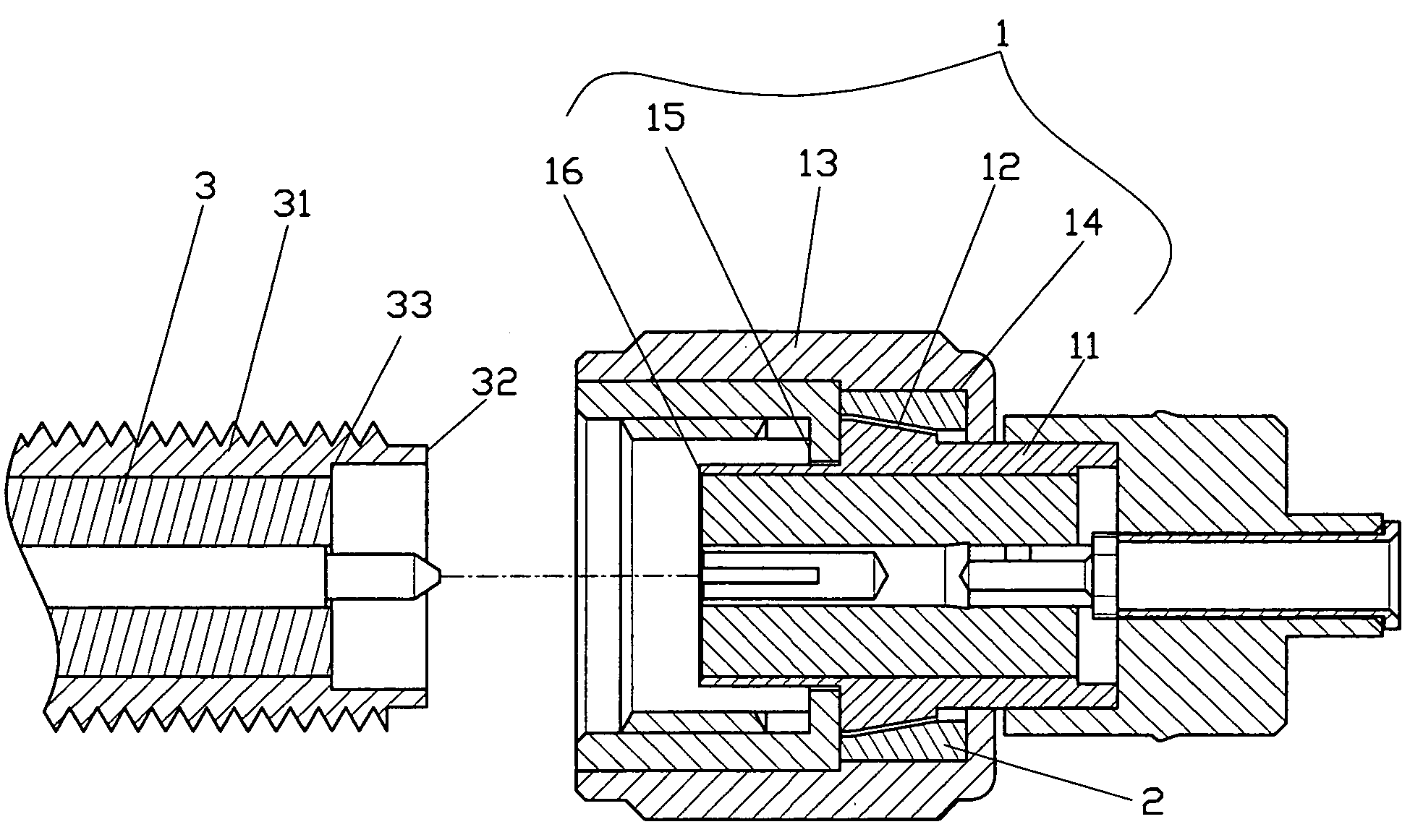
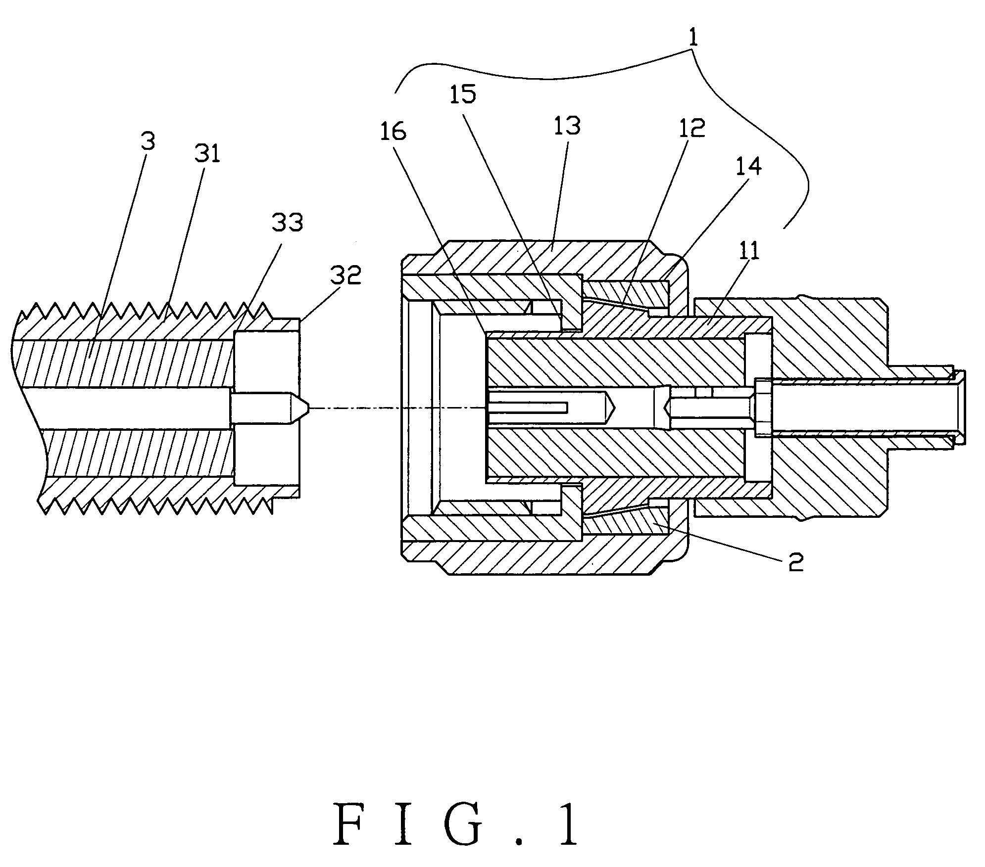
[0014]The present invention comprises a male connector 1, an elastic element 2 and a female connector 3.

[0015]The male connector 1 has a main body 11. The main body 11 has a taper section 12 on the outer edge thereof. A turning part 13 is sleeved on the main body 11 with a recess 14 formed between the turning part 13 and the taper section 12 of the main body 11. The turning part 13 has a first end 15 therein, while the main body 11 has a second end 16 thereon.

[0016]The elastic element 2 is disposed in the recess 14 of the male connector 1. The elastic element 2 is shaped like a wedge and made of silica gel.

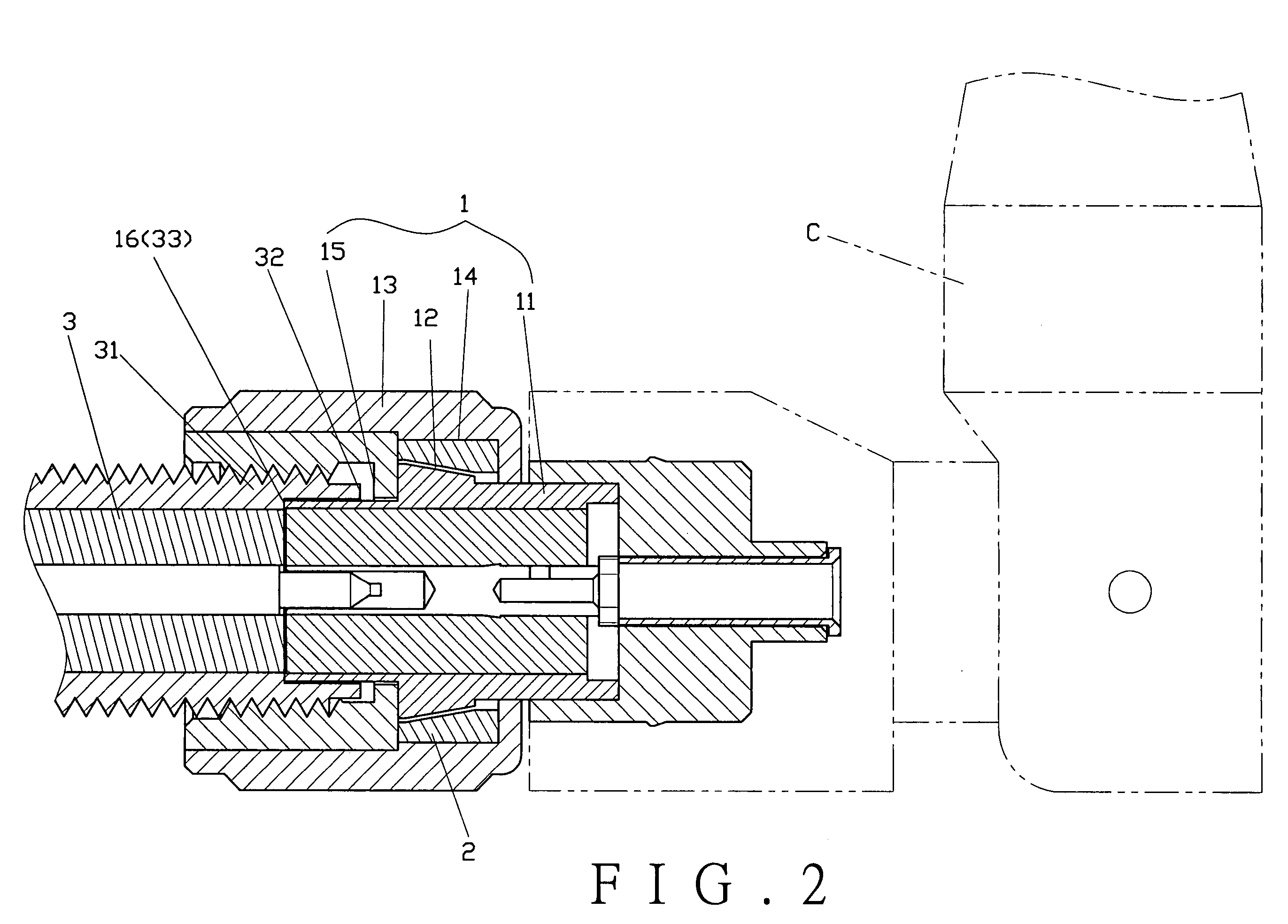
[0017]The female connector 3 is screwed to the male connector 1 and comprises a case 31. The case 31 has a first end 32 thereon, while the female connector 3 has a second end 33 therein.

[0018]To assemble the present invention, as shown in FIG. 2, the main body 11 of the male connector 1 is connected to an antenna C. When rotating the antenna C, the main body 11 will also rotate si...


PUM


Abstract

A connecting device for an antenna includes a taper section provided on a main body of a male connector and a recess formed between the taper section and a turning part. A wedge-shaped elastic element is disposed in the recess for forcing the elastic element towards the taper section to secure the male and female connectors together. First ends and second ends of the male and female connectors are in a full contact, providing a high frequency signal transmission.

Description

BACKGROUND OF THE INVENTION[0001]1. Field of the Invention[0002]This invention relates to a connecting device for an antenna, and more particularly to a recess formed between a taper section of a main body and a turning part for receiving an elastic element, urging the elastic element to maintain a good contact of first ends and second ends of a male connector and a female connector.[0003]2. Description of Prior Art[0004]An antenna structure currently used on the market, as shown in FIG. 4, comprises a male connector A and a female connector B. The male connector A has a main body A1 with a turning part A2 sleeved thereon. The main body A1 is connected with an antenna C. When rotating the antenna C, the main body A1 also rotates simultaneously. A spring A3, a washer A4 and an elastic element A5 are provided between the main body A1 and the turning part A2. When the male connector A and the female connector B are screwed together, the spring A3 will force the washer A4, which in turn...

Claims


Application Information

Patent Timeline
IPC IPC(8): H01R13/62H01R4/38
CPCH01R13/622H01R13/631H01R2201/02
Inventor LIN, KUOTUNG
Owner HUANG LIANG PRECISION ENTERPRISE
Why Eureka
Try Eureka