Control arrangement for crop discharging device of an agricultural harvesting machine

a technology of agricultural harvesting machine and control arrangement, which is applied in the direction of digger harvester, loading/unloading, agricultural tools and machines, etc., can solve the problems of limited number of storable positions of the discharging device and arrangement can only function

Active Publication Date: 2006-06-20
DEERE & CO
View PDF20 Cites 27 Cited by
  • Summary
  • Abstract
  • Description
  • Claims
  • Application Information

AI Technical Summary

Benefits of technology

[0011]In this way, the position of the second actuator is automatically adjusted to that of the first actuator. Thus, it is not necessary for the operator to manually adjust the second actuator when the first actuator is adjusted to respond to a changed situation. This is so because the second actuator is adjusted automatically via the position controlling arrangement. In an embodiment, the controller operates electronically and the actuators are moved electromechanically or by electronically controlled means which are pneumatically or hydraulically mediated. In another embodiment, the position controlling arrangement works hydraulically, with a first master cylinder which is moved by the first actuator and controls the second actuator hydraulically.
[0012]In particular, the second actuator can be controlled such that the discharge height, i.e., the height of the outflow from the crop discharging device, is maintained when the crop discharging device is moved (e.g. rotated around the vertical axis). This embodiment is particularly advantageous if the first actuator executes a rotation around an axis which is approximately but not precisely vertical. Thus the controller compensates for the change in height of the outflow from the crop discharging device when the latter is rotated around the approximately vertical axis.

Problems solved by technology

The number of storable positions of the discharging device is limited, however, and is insufficient for situations in which the relative positions of the harvesting machine and the transporting vehicle change.
However, this arrangement can only function if the transport vehicle is traveling on a predefined path, e.g. if the transport vehicle constantly travels behind the chopper or is pulled by the chopper.

Method used


Image

  • Control arrangement for crop discharging device of an agricultural harvesting machine
  • Control arrangement for crop discharging device of an agricultural harvesting machine
  • Control arrangement for crop discharging device of an agricultural harvesting machine

Examples


Embodiment Construction

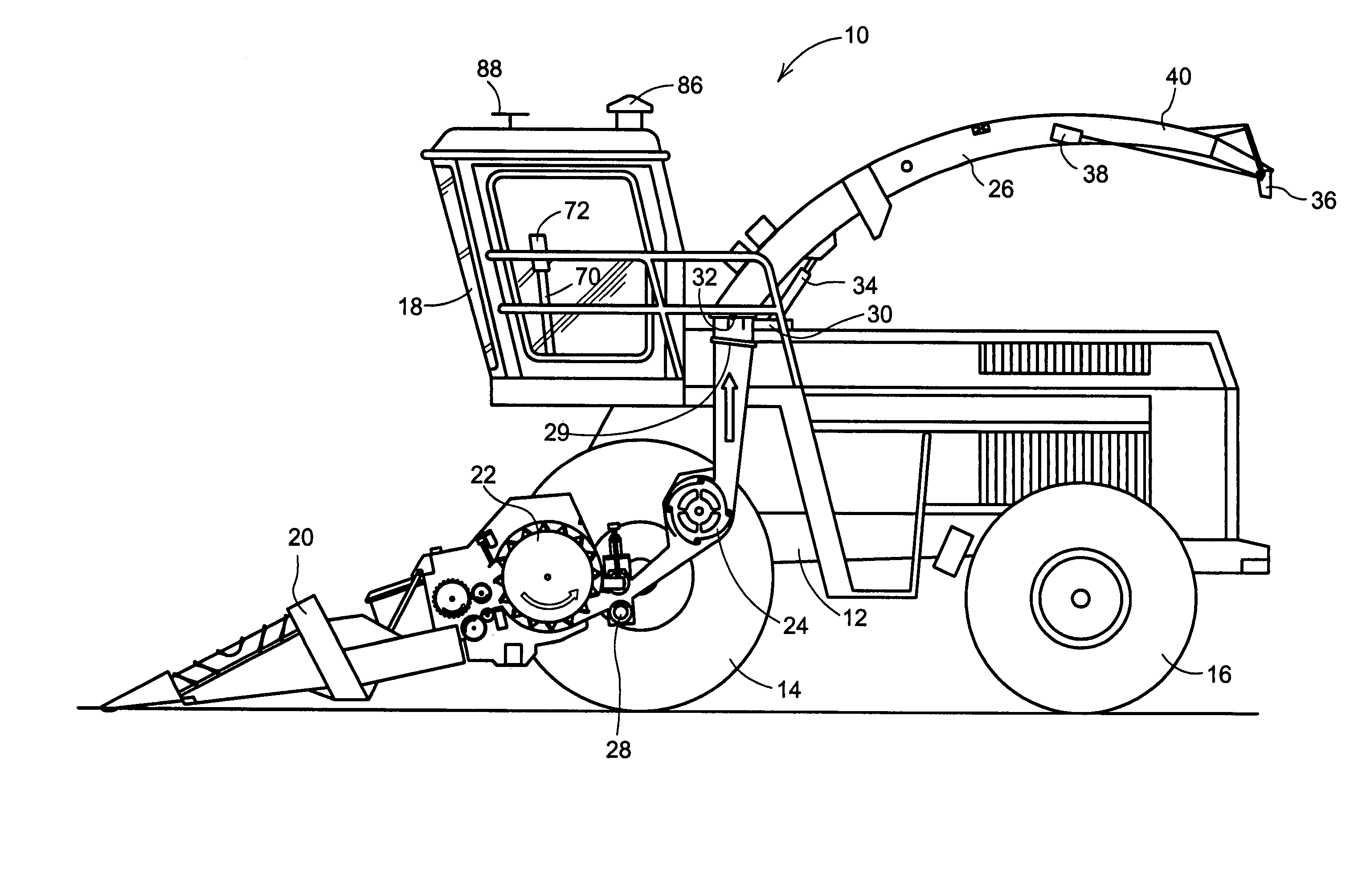
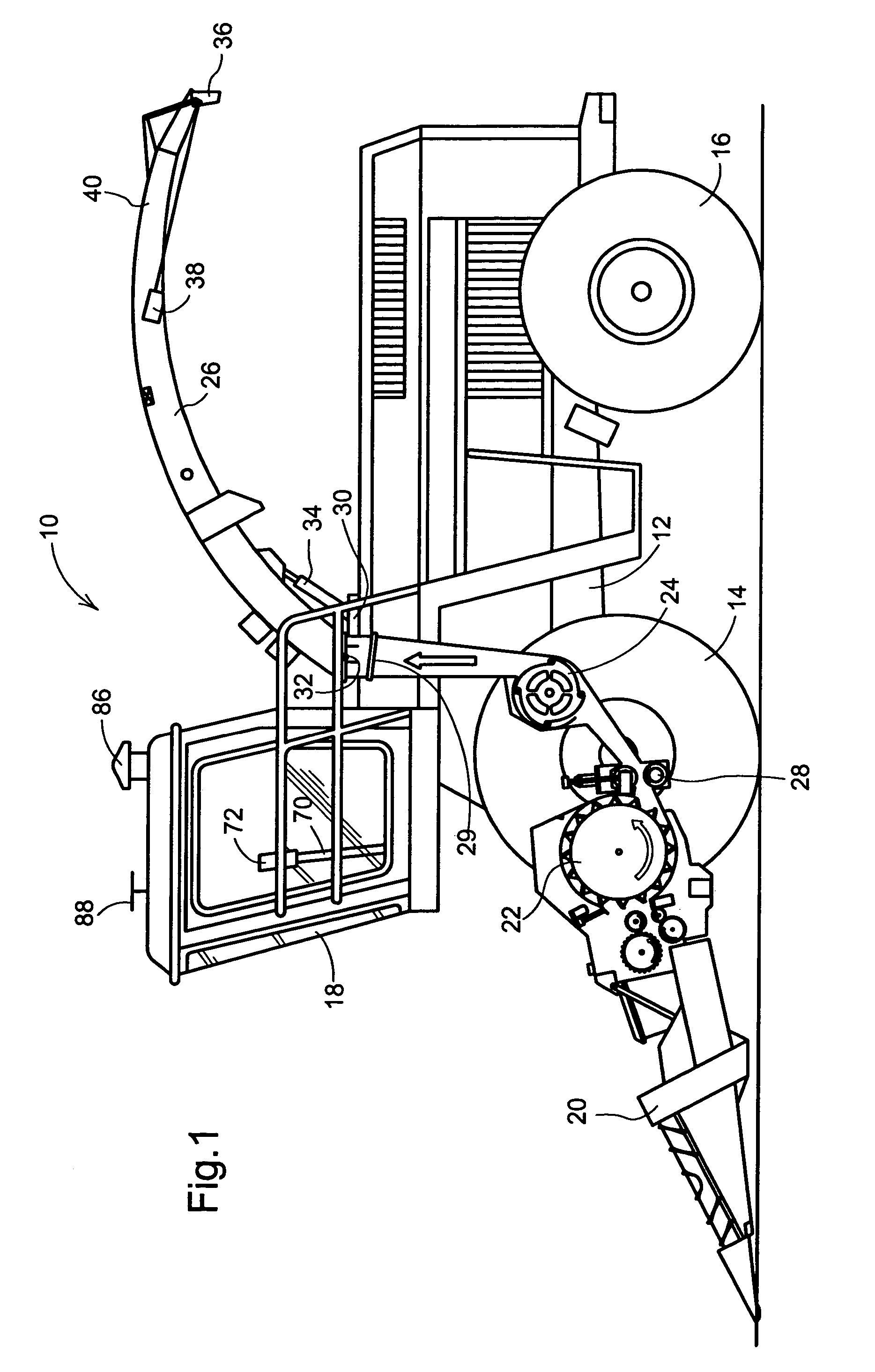
[0022]The harvesting machine 10, shown in FIG. 1 in the form of a self-propelled chopper, is comprised of a frame 12, which is borne on front wheels 14 and rear wheels 16. The harvesting machine 10 is operated from an operator's cabin 18 from which a harvested material intake device 20 is visible. The material harvested from the ground, e.g. corn, grass, or the like, is introduced to a chopping drum 22 via the intake device 20. There the harvested material is chopped into small pieces and is transferred to a conveying device 24. The harvested material passes from the harvesting machine 10 to a transport vehicle which is being driven nearby, via a crop discharging device 26 in the form of a rotatable discharge spout. A device for further fragmentation, shown here as a kernel processor 28, extends between the chopping drum 22 and the conveying device 24. The kernel processor 28 feeds the material to be conveyed tangentially to the conveying device 24.

[0023]The position of the crop dis...


PUM


Abstract

A crop discharging device, such as a discharge spout for a crop chopping machine, has a crop input end mounted for swiveling about an inclined upright axis and for pivoting vertically about a horizontal axis. The discharge spout also includes a vertically adjustable flap at its discharge end for directing the flow of crop from the spout. A first actuator is provided for effecting movement of the spout about the upright axis, a second actuator is provided for effecting movement of the spout about the horizontal axis and a third actuator is provided for effecting movement of the flap. A control arrangement, which includes a memory into which a preset correlation table, or the like may be loaded, is provided for automatically controlling the position of the second actuator as a function of the position of the first actuator so as to maintain a given discharge height. In the same way, the control arrangement is capable of automatically controlling the third actuator as a function of the operation of the second actuator so as to maintain a desired direction of flow of the crop from the spout during adjustment of the height of the discharge end of the spout.

Description

FIELD OF THE INVENTION[0001]The invention relates to a crop discharging device of an agricultural harvesting machine, having a first actuator and a second actuator which are connected to an arrangement for controlling their position and are arranged to alter the position of a crop conveying part of the discharging device.BACKGROUND OF THE INVENTION[0002]In current practice in the harvesting of agricultural crops in the field, the harvesting machine loads the harvested material into a transport vehicle which is driven along near the harvesting machine. The transport vehicle may be, e.g., a tractor-trailer combination or a truck. The harvested material is loaded into the transport vehicle via a crop discharging device associated with the harvesting machine. E.g., if the harvester comprises a chopper, the crop discharging device may comprise a spout, and if the harvester comprises a thresher, the crop discharging device may comprise a discharge auger. As a rule the crop discharging dev...

Claims


Application Information

Patent Timeline
Patent Type & Authority Patents(United States)
IPC IPC(8): A01F12/46A01D43/08
CPCA01D43/087
Inventor VOGELGESANG, CLAUS JOSEFSCHAEFER, PETER
Owner DEERE & CO
Why Eureka
Try Eureka