Motor drive system for AC motors

a technology of ac motors and motor drives, which is applied in the direction of electronic commutators, dynamo-electric converter control, dynamo-electric gear control, etc., can solve the problems of difficult to capture a motor current component, difficult to reproduce a current, and extremely short gate pulses

Inactive Publication Date: 2006-06-20
HITACHI AIR CONDITIONING SYST +2
View PDF8 Cites 35 Cited by
  • Summary
  • Abstract
  • Description
  • Claims
  • Application Information

AI Technical Summary

Benefits of technology

[0008]In a motor drive system for AC motors, to detect a current from a DC power supply of the inverter, the inverter current is sampled in the proximity of an intermediate time of each conduction time period, and on the basis of sampled values, an applied voltage to the motor or frequency is controlled.

Problems solved by technology

With the current reproducing method, however, which reproduces a motor current on the basis of the inverter's input DC current and a gate pulse signal, it is difficult to capture a motor current component when the gate pulse is extremely short.
Above all else, the higher the average switching frequency (carrier frequency) is set, the shorter the gate pulse becomes, making it more difficult to reproduce a current.
As an antidote for this, if measures are taken to set a lower carrier frequency of the inverter, this increases higher harmonics of the current, which causes lower efficiency and results in occurrence of electromagnetic noise.

Method used


Image

  • Motor drive system for AC motors
  • Motor drive system for AC motors
  • Motor drive system for AC motors

Examples


embodiment 1

(Embodiment 1)

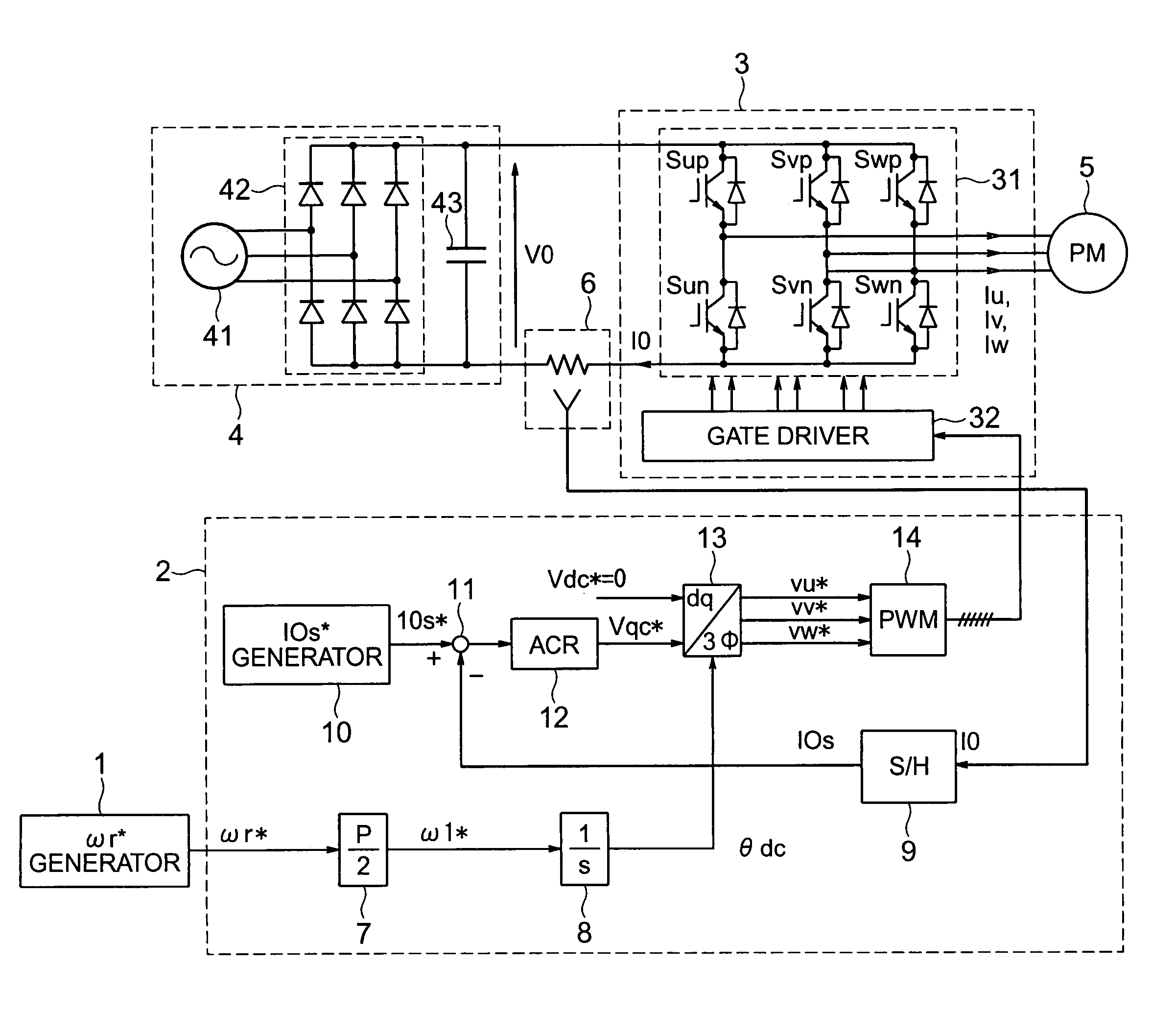
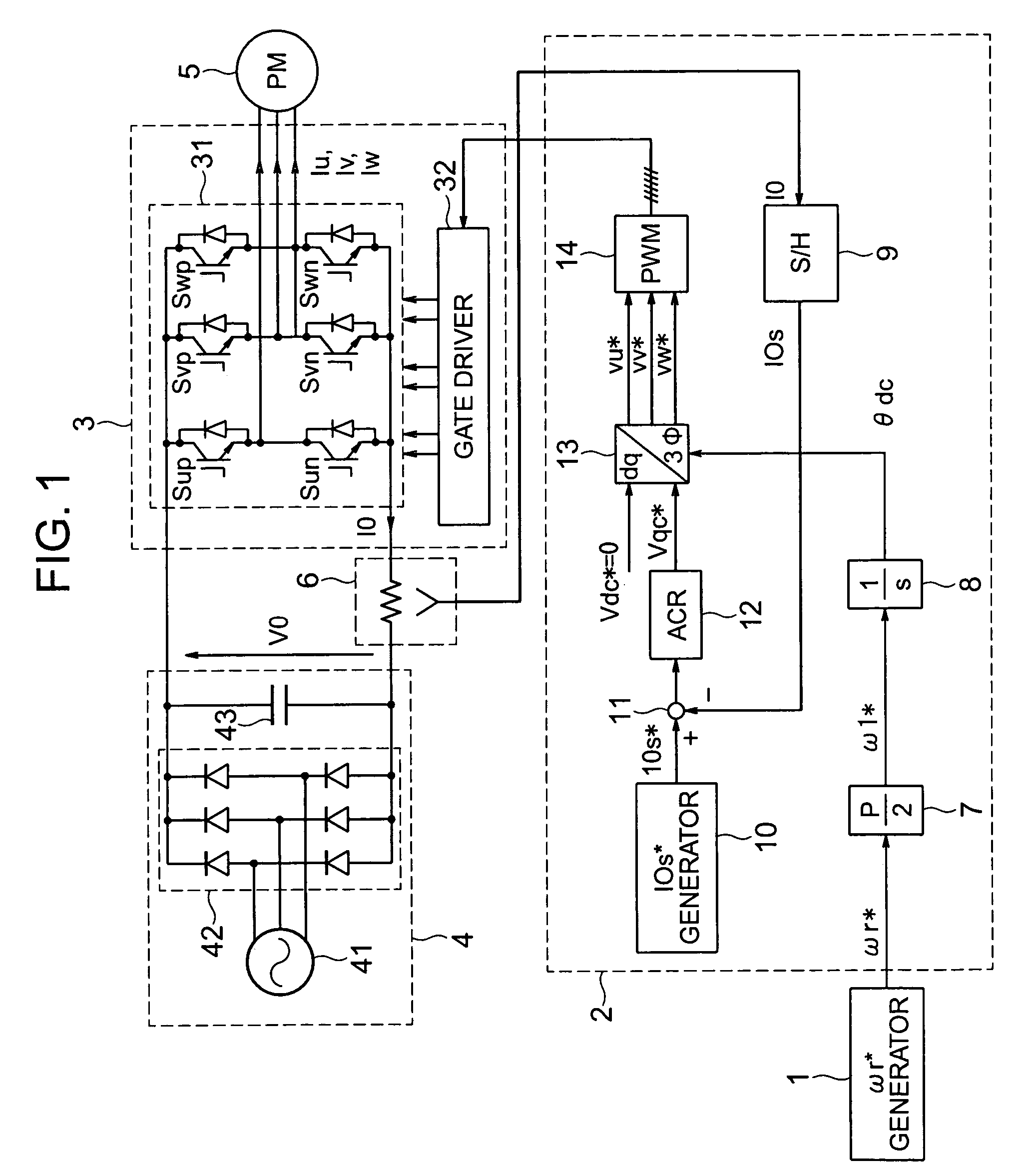
[0028]FIG. 1 is a block diagram showing a system structure according to a first embodiment of an AC motor drive system of the present invention. A motor drive system of this embodiment comprises a rotation number command generator 1 for sending a rotation number command ωr* to a motor, a controller 2 for computing an AC voltage applied to the motor, converting it into a pulse-width-modulated signal (PWM signal), and outputting this PWM signal, an inverter 3 driven by this PWM signal, a DC power supply 4 for supplying electric power to the inverter 3, a permanent magnet type motor 5 as a controlling object, and a current detector 6 for detecting a current Ic supplied to the inverter 3.

[0029]The controller 2 comprises a conversion gain 7 for converting a rotation number command ωr* into an electrical angular frequency command ω1* of the motor 5 by using a pole number P of the motor, an integrator 8 for computing an AC phase θdc in the motor drive system, a current sample...

embodiment 2

(Embodiment 2)

[0049]Referring to FIG. 8, description will be made of a second embodiment of the present invention.

[0050]In the first embodiment, a current is provided in such a manner that the current flowing in the motor becomes a predetermined current value. In contrast, the second embodiment has as its object to detect a “reactive current” that flows in the motor to thereby control the motor with high performance.

[0051]FIG. 8 shows a block diagram of a controller 2A. Instead of the controller 2 in FIG. 1, the controller 2A in FIG. 8 is used which enables the second embodiment to be realized. In FIG. 8, the blocks which differentiate the second embodiment from the first embodiment are a filters 15 for los, aω1 compensator 16 that adds Δω1 to an electrical angular frequency command ω1* of the motor on the basis of output of the filter 15, and a voltage command computing unit 17 that decides a voltage applied to the motor from ω1*.

[0052]The controller 2A does not control the current...

embodiment 3

(Embodiment 3)

[0064]Referring to FIGS. 10 and 11, a third embodiment of the present invention will be described. FIGS. 10 and 11 show a method for detecting a reactive current and an example in which this method was applied to control.

[0065]FIG. 10 is a block diagram of a controller 2C. Instead of the controller 2 in FIG. 1, by using the controller 2C in FIG. 10, the third embodiment can be realized. In FIG. 10, the parts that differentiate the controller 2C from the controllers 2 and 2A in the above-mentioned embodiments are: an Ia·Ir computing unit 18 for computing at least one of the active current Ia and the reactive current Ir, which flow in the motor, from Ios; an interrupt generator 19 for generating an interrupt to start computing in the Ia·Ir* computing unit 18; and an Ir* generator 20 for giving a current command Ir* to the reactive current Ir.

[0066]Then, description will be made of the operation principle of the third embodiment. The Ia·Ir computing unit 18 computes an ac...


PUM


Abstract

A motor drive system without any portion for directly detecting the rotor position, rotation speed and motor phase currents, capable of realizing a high-performance variable speed drive even at high carrier frequencies. When detecting a current from a DC power supply of an inverter for driving a motor, applied voltages and frequencies to the motor are controlled based on sampled values by sampling a current flowing as intermittent pulses in the vicinity of each power conduction time period.

Description

BACKGROUND OF THE INVENTION[0001]1. Field of the Invention[0002]The present invention relates to a motor drive system and a control method for AC motors.[0003]2. Description of the Related Art[0004]As a control method without using a rotation speed sensor or a position sensor of an AC motor, a motor drive system has been well known which detects phase currents of a motor as disclosed in JP-A-2001-251889, for example.[0005]As a method without using a current sensor, there has been proposed, for example in JP-A-2-197295, a current reproducing method which detects a DC current of the inverter to drive a motor and reproduces an AC current of the motor from an instantaneous DC-current value detected and also from the switching states of the inverter. In this method, gate pulses to drive the inverter are used, a motor current which instantaneously appears in the DC current of the inverter is sampled and held, and thus, a motor current is indirectly detected.[0006]With the current reproduc...

Claims


Application Information

Patent Timeline
Patent Type & Authority Patents(United States)
IPC IPC(8): H02P27/04H02P6/18H02P6/06H02P6/08H02P6/17H02P6/182H02P6/28H02P21/00H02P21/22H02P23/07H02P25/22H02P27/08
CPCH02P21/0039H02P21/00H02P21/24
Inventor IWAJI, YOSHITAKAENDO, TSUNEHIROSAKAMOTO, KIYOSHIOKUBO, TOMOFUMI
Owner HITACHI AIR CONDITIONING SYST
Why Eureka
Try Eureka