Thin laminated single pole perpendicular write head

a write head and perpendicular technology, applied in the field of magnetic disk systems, can solve the problems of erasure of written bits and the problem of increasing the size of the device, and achieve the effects of low net magnetic moment, low interlayer exchange coupling energy, and low net magnetic momen

Inactive Publication Date: 2006-06-20
HEADWAY TECH INC
View PDF12 Cites 8 Cited by
  • Summary
  • Abstract
  • Description
  • Claims
  • Application Information

AI Technical Summary

Benefits of technology

[0012]These Objects have been achieved by giving the write pole the form of a three-layer laminate in which two ferromagnetic layers are separated by an anti-ferromagnetic coupling layer or by a non-magnetic layer. If an antiferromagnetic coupling layer is used, its thickness is chosen to be optimum for antiferromagnetic coupling. In the remanent state (no external driving field), the two laminated ferromagnetic layers will stay antiparallel to each other so as to minimize the interlayer exchange coupling energy and to allow as much magnetic flux closure as possible, leaving the structure with a low net magnetic moment. For the non-magnetic layer, its thickness is chosen so that there can be no ferromagnetic exchange coupling between the ferromagnetic layers, in which case the low net magnetic moment is achieved solely through magnetic flux closure.

Problems solved by technology

After the writing process, the remnant field from a single pole can be very large (as high as 2 kOe), which usually causes erasure of written bits.
This problem will get more severe with further decreases in device dimensions.

Method used


Image

  • Thin laminated single pole perpendicular write head
  • Thin laminated single pole perpendicular write head
  • Thin laminated single pole perpendicular write head

Examples


Embodiment Construction

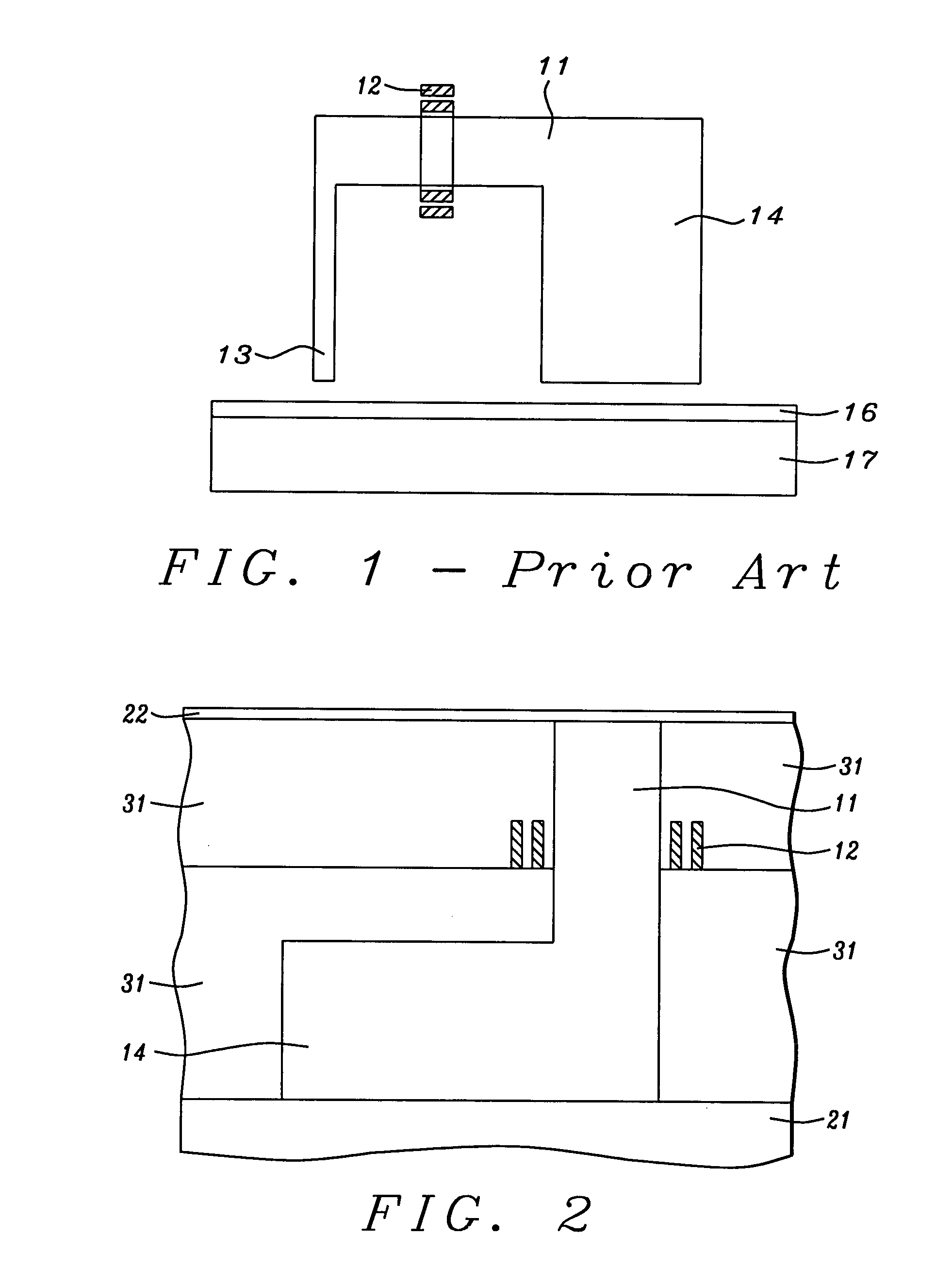
[0017]We will disclose the present invention by providing a description of a method for generating it, thereby making the structure of the invention apparent as well. Referring now to FIG. 2, the method begins with the provision of magnetic yoke 11 which had previously been deposited and patterned on return pole 14 which is shown in contact with substrate 21 (commonly a magnetic shield).

[0018]Conductive coil 12 is also formed so that it surrounds yoke 11. The various incidences of layer 31 that appear in the figure represent insulating, non-magnetic material that serves to provide mechanical integrity to the structure.

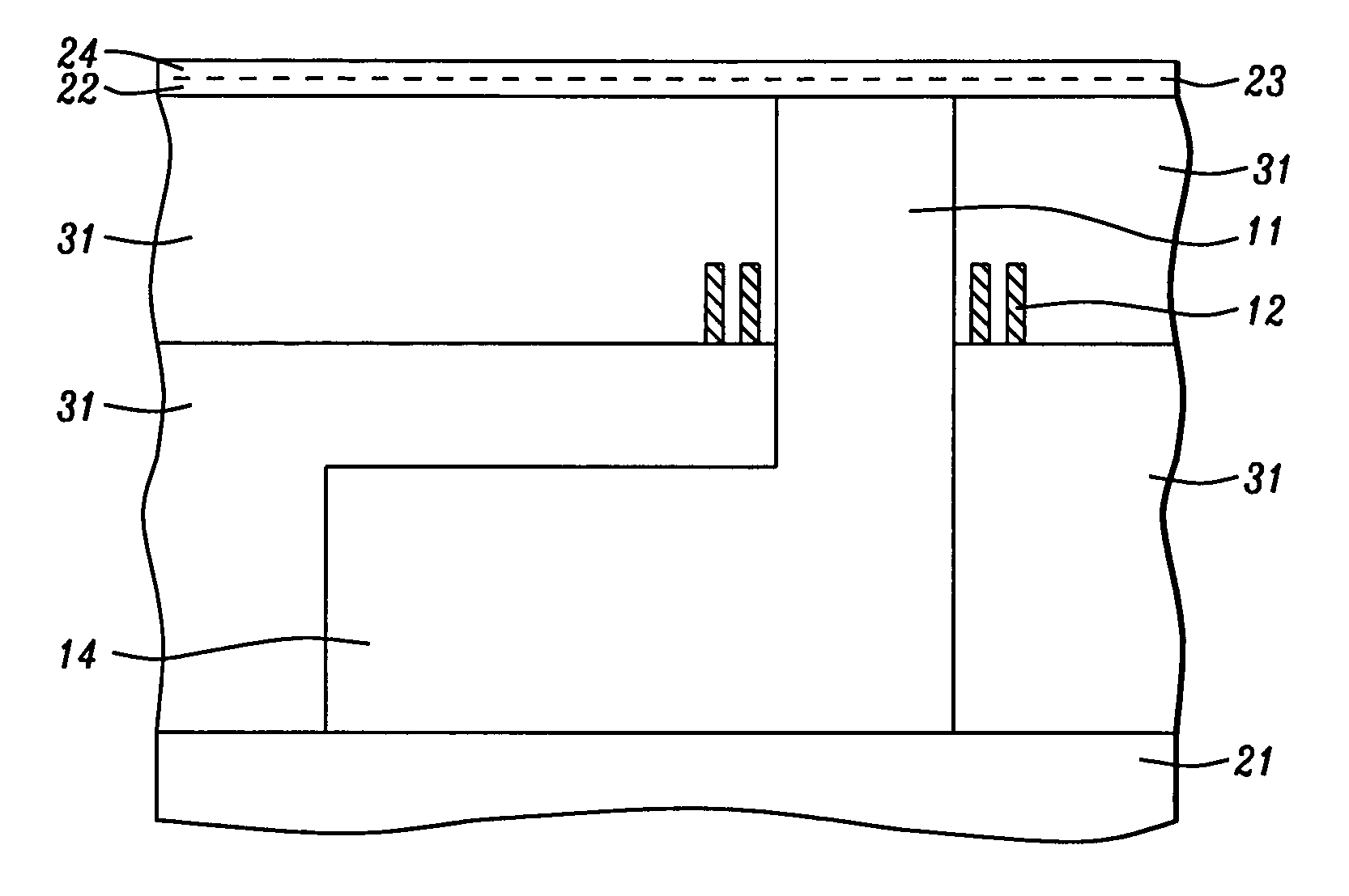
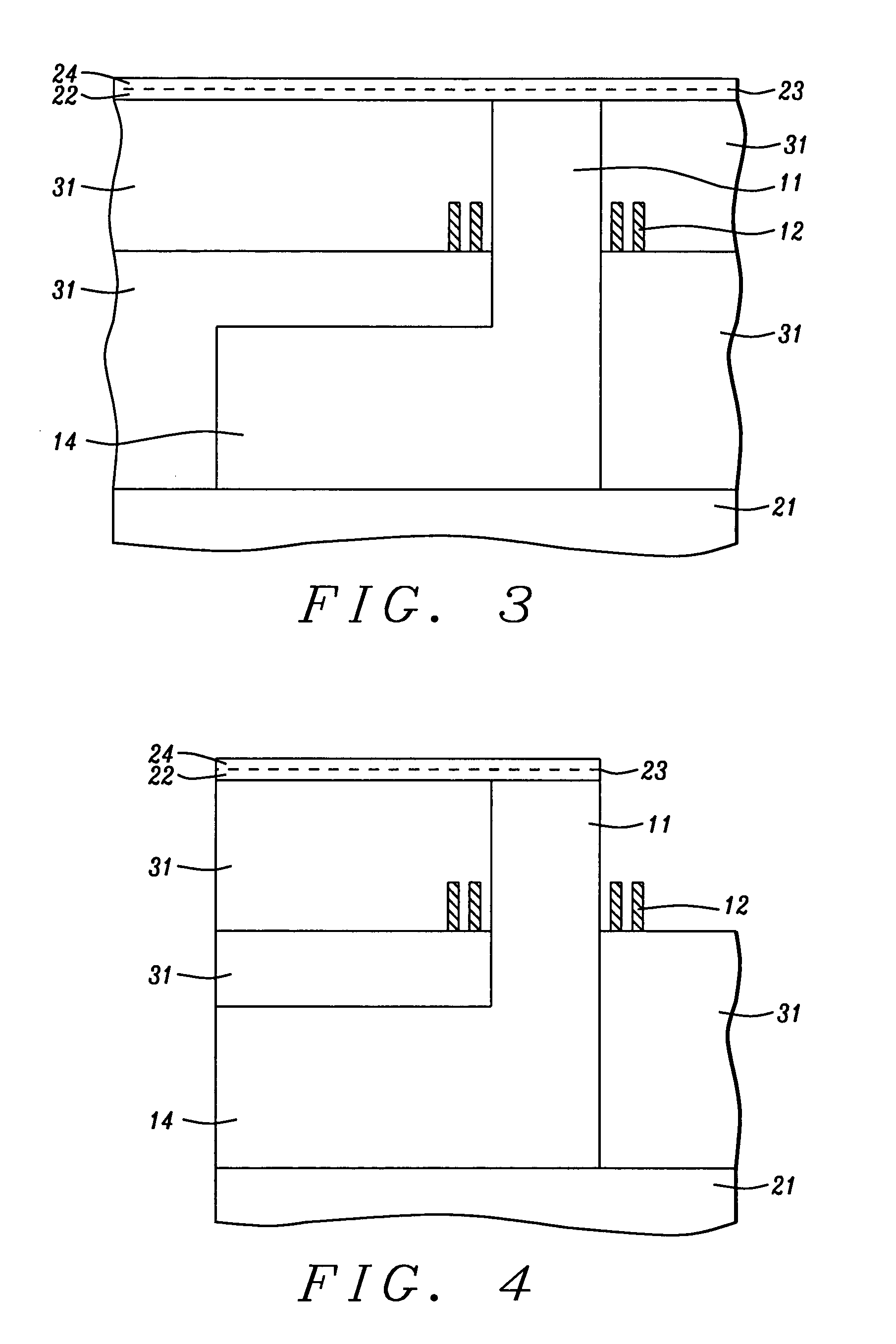
[0019]Normally, the next step would be to deposit the full thickness of the write pole. However, in a departure from the prior art, a first (lower) layer of ferromagnetic material 22 is deposited onto the topmost surface of 31 as well as onto the exposed surface of yoke 11, giving the structure, at this stage, the appearance seen in FIG. 2. For lower ferromagnetic laye...


PUM

PropertyMeasurementUnit
thicknessaaaaaaaaaa
thicknessaaaaaaaaaa
thicknessaaaaaaaaaa

Abstract

Single write poles tend to large shape anisotropy which results in a very large remnant field when not actually writing. This has now been eliminated by giving the write pole the form of a three layer laminate in which two ferromagnetic layers are separated by a non-magnetic or antiferromagnetic coupling layer. Strong magnetostatic coupling between the outer layers causes their magnetization directions to automatically be antiparallel to one another, unless overcome by the more powerful write field, leaving the structure with a low net magnetic moment. The thickness of the middle layer must be carefully controlled.

Description

FIELD OF THE INVENTION[0001]The invention relates to the general field of magnetic disk systems with particular reference to magnetic write heads for perpendicular designs, more specifically to remnant field reduction in single pole heads.BACKGROUND OF THE INVENTION[0002]Perpendicular magnetic recording (PMR) is important for the future of the magnetic recording industry because it offers higher areal density than the current longitudinal magnetic recording (LMR). This is due to the fact that the PMR medium is thermally more stable than that used for LMR. At present, LMR has achieved over 100 Gigabits per square inch (Gbpsi) in the laboratory and more than 60 Gpsi in products currently offered at the market place. In order to further extend the LMR recording density, two main obstacles have to be overcome. The first one is the thermal stability of the LMR recording media which arises because its thickness has to decrease to the extent that thermal energy could randomize the recorded...

Claims


Application Information

Patent Timeline
Patent Type & Authority Patents(United States)
IPC IPC(8): G11B5/147G11B5/127G11B5/187G11B5/245G11B5/31G11B5/465
CPCG11B5/1278G11B5/187G11B5/245Y10T29/49032G11B5/465Y10T29/49043G11B5/3156
Inventor JU, KOCHANGUAN, LIJIECHANG, JEIWEILI, MINHU, BEN
Owner HEADWAY TECH INC
Why Eureka
Try Eureka