Image forming apparatus with variable fixing heat
a technology of fixing unit and heat transfer, which is applied in the direction of electrographic process apparatus, instruments, optics, etc., can solve the problems of long waiting time, overshooting of temperature of fixing unit b>24/b>, and inability to meet the requirements of large heat capacity, etc., to achieve the effect of avoiding overshooting, hot offset and long waiting tim
- Summary
- Abstract
- Description
- Claims
- Application Information
AI Technical Summary
Benefits of technology
Problems solved by technology
Method used
Image

Examples
first embodiment
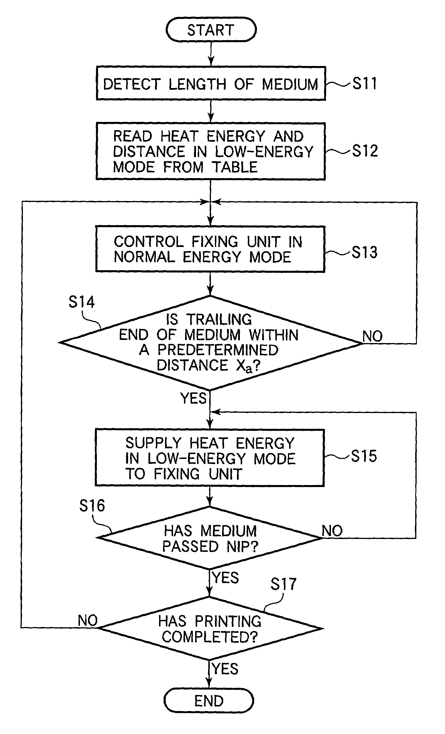
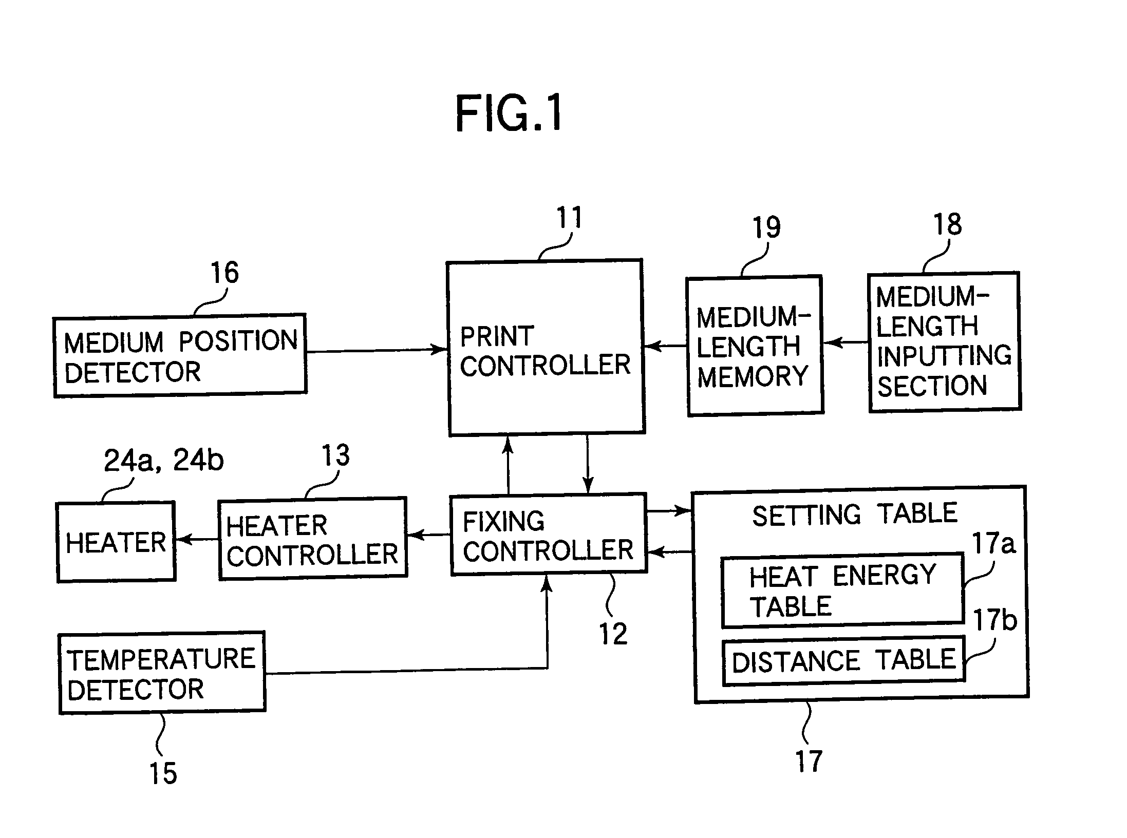
[0070]FIG. 1 illustrates the configuration of an image forming apparatus according to a first embodiment. Elements similar to those described in “DESCRIPTION OF THE RELATED ART” have been given the same reference numerals and the description thereof is omitted.
[0071]Referring to FIG. 1, a fixing controller 12 communicates with a print controller 11. The print controller 11 is connected to a medium position detector 16, a medium length memory 19, and a medium length inputting section 18. Reference is made to FIGS. 15–17 and FIGS. 18A and 18B and the associated descriptions for the configuration of the image forming apparatus according to the present invention.
[0072]The fixing controller 12 communicates with a heater controller 13, heaters 24a and 24b, and a temperature detector 15. The temperature detector 15 detects the temperatures of, for example, the heat rollers in the fixing unit 24. The heaters 24a and 24b take the form of, for example, a halogen lamp but may be of any type of...
second embodiment
[0109]Elements similar to those in the first embodiment have been given the same reference numerals and the description thereof is omitted.
[0110]FIG. 6 illustrates the configuration of a controller for an image-forming apparatus according to a second embodiment.
[0111]The second embodiment differs from the first embodiment in that a medium length detector 28 is used in place of the medium length inputting section 18 and the medium length memory 19.
[0112]The operation of the image-forming apparatus of the aforementioned configuration will be described.
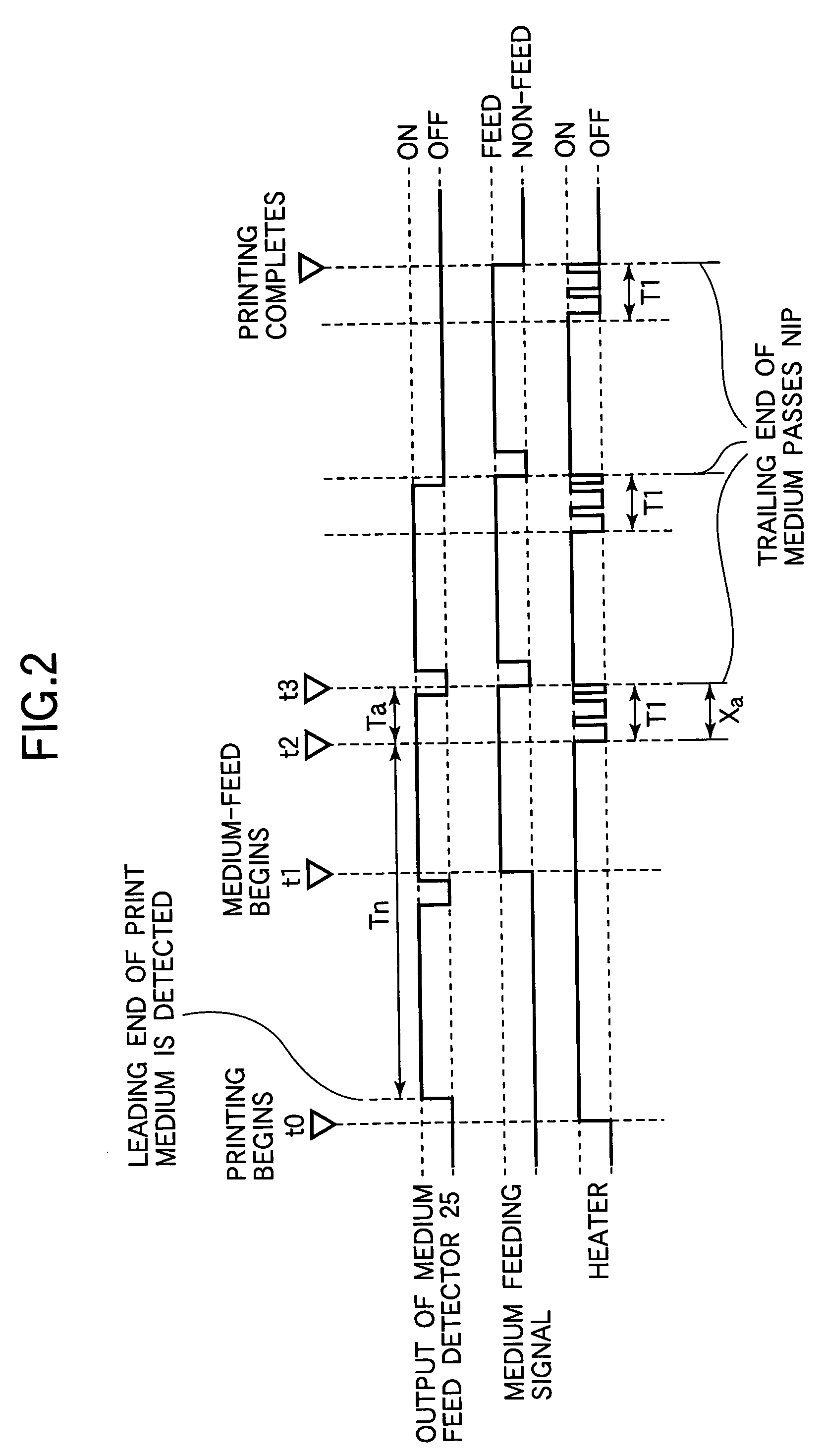
[0113]FIG. 7 is a timing chart illustrating the status of pertinent sections during printing according to the second embodiment. The heaters 24a and 24b are turned on or off when the temperature of the heat rollers is out of a predetermined range. This predetermined range is much narrower than an acceptable temperature range (FIG. 4) of the heat rollers. FIG. 7 assumes that the temperature of the heat rollers of the fixing unit 24 is low...
third embodiment
[0135]Elements similar to those in the first and second embodiments have been given the same reference numerals and the description thereof is omitted. Changes in printing conditions such as environment and printing speed causes changes in the amount of heat required to be supplied to the print medium 23. The amount of heat that should be supplied from a fixing unit 24 changes accordingly. In a third embodiment, the amount of heat to be supplied to the fixing unit 24 is corrected in accordance with printing conditions, thereby preventing the temperature of the fixing unit 24 from overshooting to eliminate cold offset.
[0136]FIG. 9 illustrates the configuration of an image-forming apparatus according to the third embodiment.
[0137]Referring to FIG. 9, the configuration of the third embodiment is much the same as the second embodiment except that an environment detector 29 is coupled to a print controller 11.
[0138]The operation of the image-forming apparatus of the aforementioned config...
PUM
 Abstract
Description
Claims
Application Information
 - R&D
- Intellectual Property
- Life Sciences
- Materials
- Tech Scout
- Unparalleled Data Quality
- Higher Quality Content
- 60% Fewer Hallucinations
Browse by: Latest US Patents, China's latest patents, Technical Efficacy Thesaurus, Application Domain, Technology Topic, Popular Technical Reports.
© 2025 PatSnap. All rights reserved.Legal|Privacy policy|Modern Slavery Act Transparency Statement|Sitemap|About US| Contact US: help@patsnap.com