Method of steering smart antennas

a technology of antennas and antennas, applied in diversity/multi-antenna systems, sites, instruments, etc., can solve the problems of radio interference in other nodes, poor lpi (low probability of intercept) properties, and inability to have directional power gain

Inactive Publication Date: 2006-06-20
HARRIS GLOBAL COMM INC
View PDF20 Cites 32 Cited by
  • Summary
  • Abstract
  • Description
  • Claims
  • Application Information

AI Technical Summary

Problems solved by technology

A node transmitting signals via an omni-directional antenna produces radio interference in other nodes that may be receiving signals via omni-directional antennas.
Onmi-directional antennas do not have directional power gain and have poor LPI (low probability of intercept) properties.
The mobile nodes, thus, do not have directional power gain and can not avoid transmission interference from other nodes.

Method used


Image

  • Method of steering smart antennas
  • Method of steering smart antennas
  • Method of steering smart antennas

Examples


Embodiment Construction

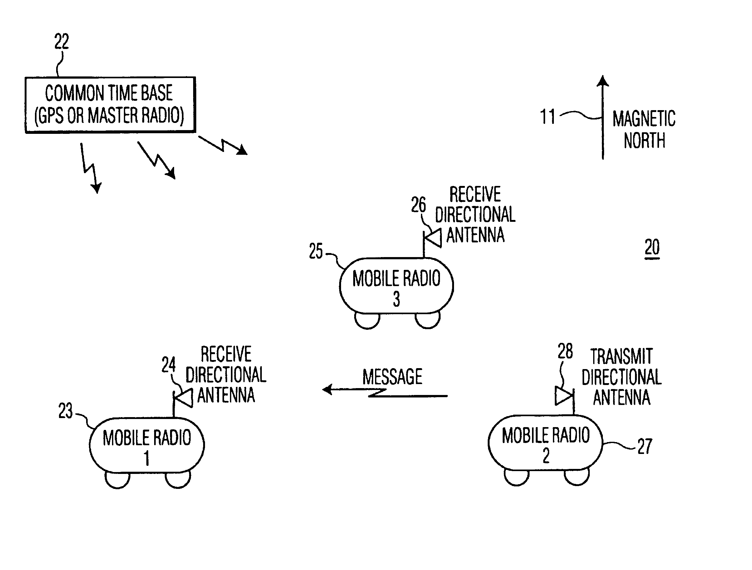
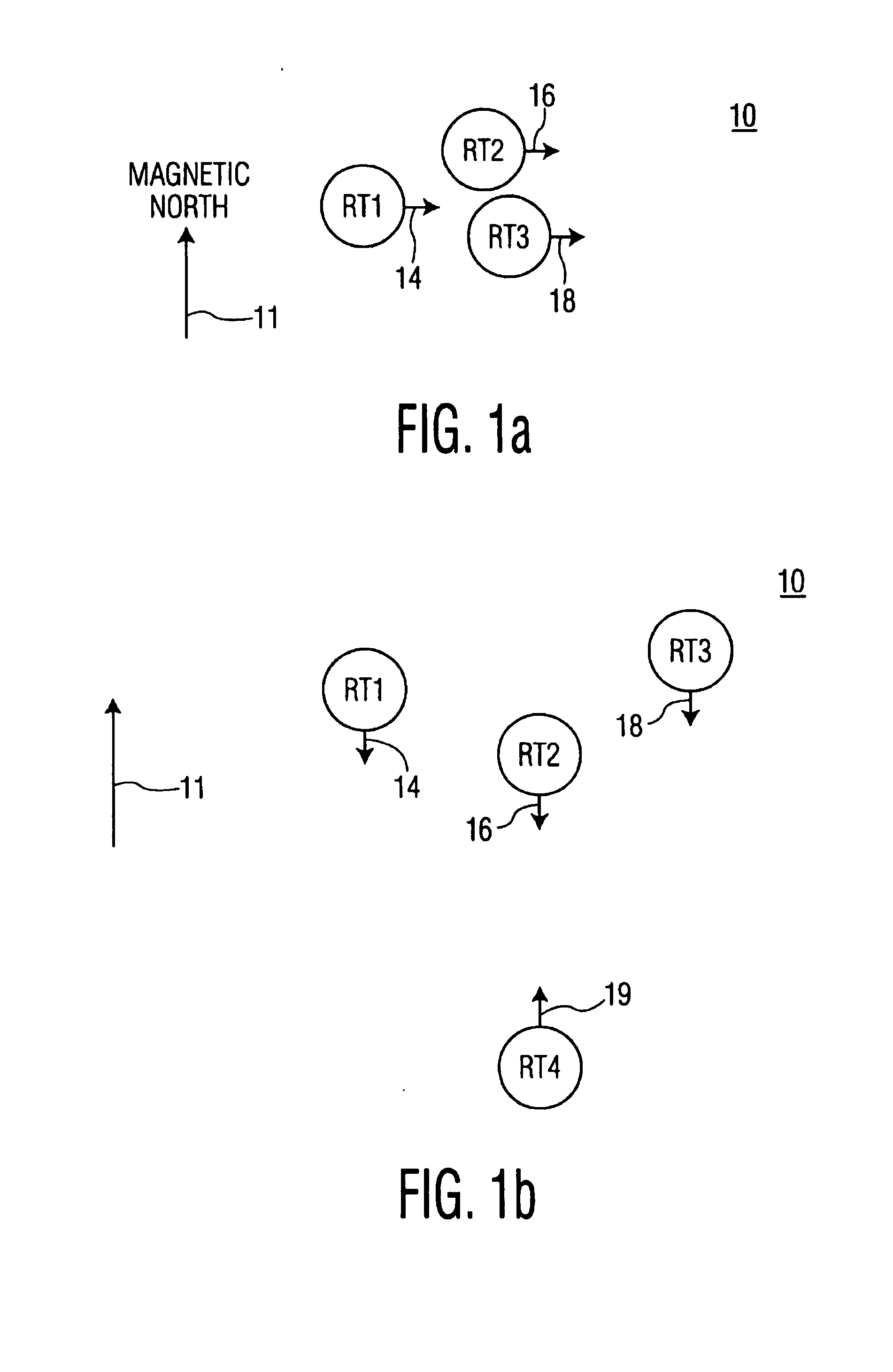
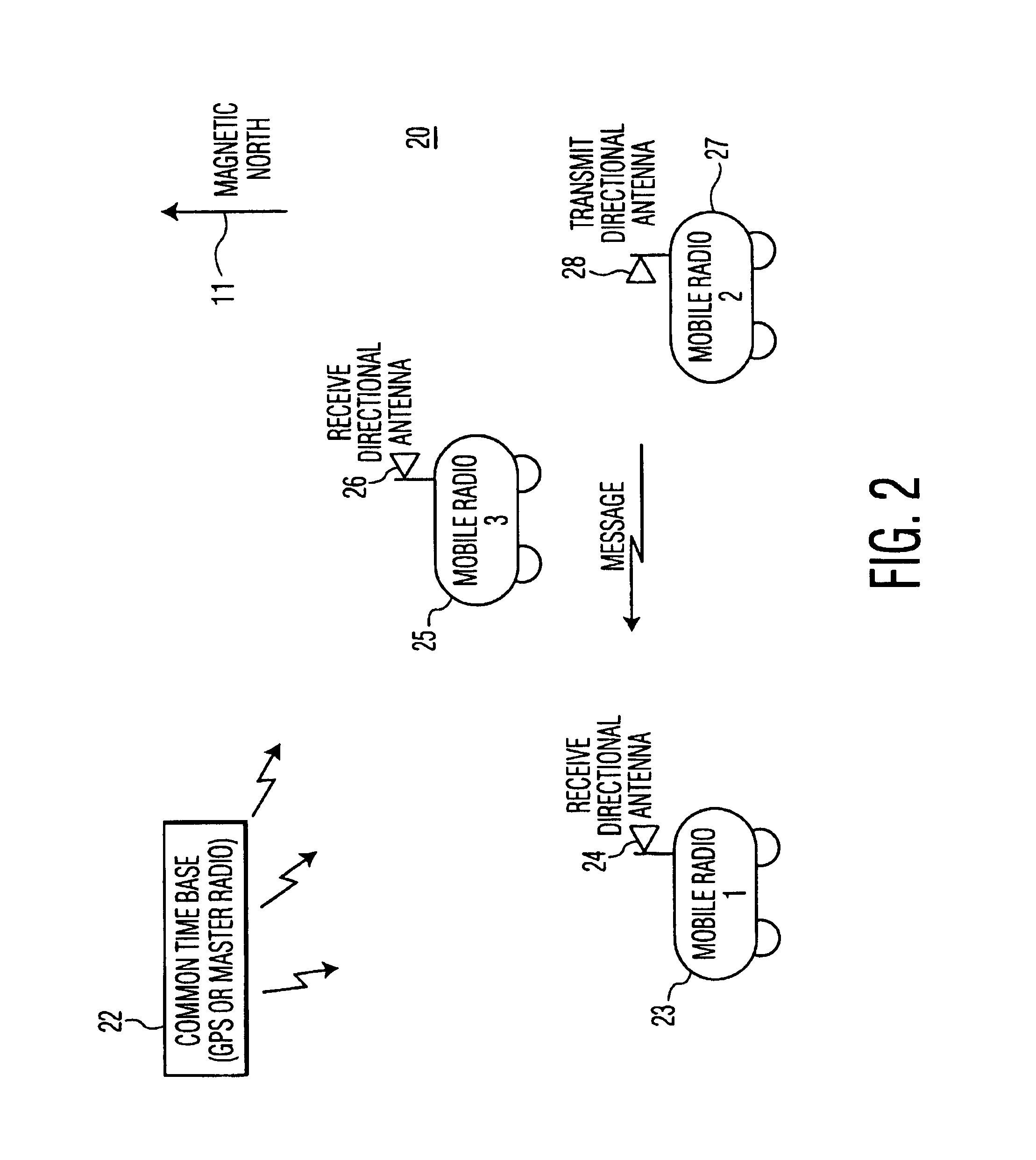
[0017]Referring now to the figures in greater detail, FIGS. 1a and 1b are block diagrams of communication network 10 in accordance with an embodiment of the present invention. As shown, communication network 10 includes multiple receivers / transmitters (also referred to herein as nodes), designated RT1, RT2, RT3 and RT4. Each node includes steerable receive and transmit antennas. In FIG. 1a, there is shown receive directional antennas 14, 16 and 18, which are steered, respectively, by RT1, RT2, and RT3. Although not shown, RT1, RT2, and RT3 each includes a transmit directional antenna, which may be time-shared or multiplexed with the receive antenna, or may be a physically separate antenna.

[0018]As will be explained, each node synchronizes the scan of its receive antenna with the scan of receive antennas of other nodes in the communication network. Each node in the network includes a similar predetermined scanning algorithm for steering its own antenna as a function of a common time ...


PUM


Abstract

The invention includes a method of communicating in a network of multiple nodes transmitting and receiving messages to and from each other. The method includes (a) scanning in synchronism a receive directional beam of an antenna of a first node and a receive directional beam of an antenna of a second node; (b) steering, in azimuth, a transmit directional beam of an antenna of the first node to a relative bearing of the second node; and (c) transmitting a message from the first node to the second node, when the transmit directional beam of the first node and the receive directional of the second node are substantially aligned in relative bearing to each other.

Description

TECHNICAL FIELD[0001]The present invention relates, in general, to a communication network that includes a plurality of nodes, each having steerable receive and transmit antenna beams. More particularly, the present invention relates to a method of synchronizing directional receive beams of the nodes and steering a directional transmit beam of a node toward a synchronized directional receive beam of another node for radio communication.BACKGROUND OF THE INVENTION[0002]Omni-directional antennas are typically used by mobile nodes communicating in a network. A node transmitting signals via an omni-directional antenna produces radio interference in other nodes that may be receiving signals via omni-directional antennas. Onmi-directional antennas do not have directional power gain and have poor LPI (low probability of intercept) properties.[0003]U.S. Pat. No. 6,353,601, issued to Siira on Mar. 5, 2002, discloses a method for space division multiple access (SDMA) wherein nodes are disting...

Claims


Application Information

Patent Timeline
Patent Type & Authority Patents(United States)
IPC IPC(8): H04B15/00H04B7/02
CPCH04B7/022
Inventor RODGERS, WILLIAM E.CHARBONNEAU, TERRANCE W.
Owner HARRIS GLOBAL COMM INC
Why Eureka
Try Eureka