Null deepening for an adaptive antenna based communication station

a communication station and antenna technology, applied in the field of wireless communication systems, can solve the problems of inability to flexibly perform this tradeoff, disturb su2, need for the base station, etc., and achieve the effects of improving uplink or downlink processing strategies, reducing transmission power, and reducing signal sensitivity

Inactive Publication Date: 2007-01-18
INTEL CORP
View PDF99 Cites 83 Cited by
  • Summary
  • Abstract
  • Description
  • Claims
  • Application Information

AI Technical Summary

Benefits of technology

[0010] An advantage of the present invention is that it provides a flexible method for directing precise and deep nulls (i.e., decreasing the transmitted power aimed at an interferer during transmission or decreasing the sensitivity to signals transmitted from the interferer during reception) on the uplink or downlink direction.
[0011] Another advantage of the present invention is that it provides a method and apparatus for estimating one or more signatures in the direction of one or more interferers.
[0012] Another advantage of the present invention is that it provides a method for using a signature estimate of an interferer for directing precise and deep nulls in the direction of the interferer.
[0013] Another advantage of the present invention is that it provides a method for directing precise and deep nulls in the direction of one or more interferers while substantially maintaining the other nulling and gain patterns of a provided adaptive smart antenna processing strategy.
[0014] Another advantage of the present invention is that it provides a null deepening method that essentially requires only an estimate signature of any interferer to deepen the null to that interferer, without needing a full set of signatures, and in particular, without needing the signature of the desired remote user.
[0015] One aspect of the invention is a method for determining, in a communication station using multiple antennas, improved uplink or downlink processing strategies, for example in the form of uplink or downlink weights for linear mart antenna processing, for which one or more nulls have a controlled depth. The method can be applied as a modification to a variety of known techniques for uplink and downlink strategy computation. The method needs as side information only the signatures of those remote users to which controlled nulls are to be directed. Other nulls in the array pattern, for which no signature estimates may be available, are substantially preserved. Another aspect of the invention includes estimating the required signatures. Another aspect of the invention modifies existing uplink and downing strategy computation methods by injecting into the received signal sequence a synthetic signal whose signature equals that of the estimated remote user direction, and whose power is proportional to the desired null depth.

Problems solved by technology

A disadvantage of known methods, such as least-squares and zero-forcing, is their inability to flexibly perform this tradeoff.
If high power is used to reach SU1 during base station transmit, then excessive signal levels leaking “through” in the imperfect null can disturb SU2.
A disadvantage of zero-forcing methods is the need for the base station to have complete knowledge of all remote user and interferer spatial signatures (or spatio-temporal signatures).
Determining all spatial signatures of all remote users and all interferers may often be impossible to carry out accurately if any of the interferers are weak or have a signal structure that is a priori unknown, or because of computational power limitations.
Thus, if a least-squares approach is used, the null depth obtained from a strategy computed for the previous burst may be inappropriate for the current burst.

Method used


Image

  • Null deepening for an adaptive antenna based communication station
  • Null deepening for an adaptive antenna based communication station
  • Null deepening for an adaptive antenna based communication station

Examples


first embodiment

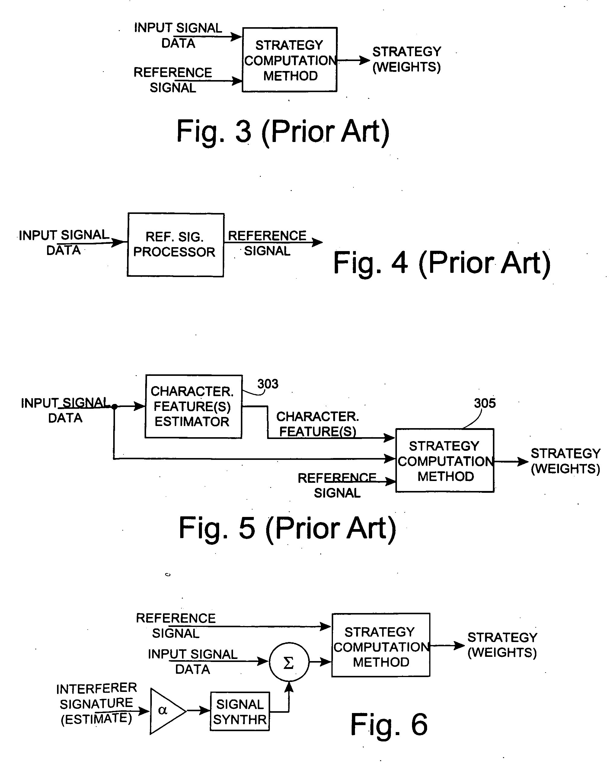
[0084] the invention applicable to one null-deepening based on the known or estimated signature of one interferer denoted SUj with signature (estimate) aj is shown in FIG. 6. A signal formed from the estimated or known interferer signal is scaled and added to the received signal data Z before determining the strategy, that is, modified received signals described by

{circumflex over (Z)}=Z+αjâjssynth,

with αj a tunable scale factor for any interferer j. ssynth is any signal that has the same temporal structure as a typical communication waveform used in the system, or preferably, a temporal structure that would be identified by the particular strategy computation method as not that of the user. For example, for a constant modulus property restoral method, using a non-constant modulus structure for ssynth ensures that the strategy computation method recognizes this as an interferer. In the preferred embodiment, however, ssynth comprises N random noise samples. In another embodiment, t...

third embodiment

[0096] A third embodiment is applicable to strategy determining methods that use an estimate of the spatial or spatio-temporal covariance (including the interference-plus-noise covariance) determined from the input signal (and possible a reference signal) to determine the strategy. The methods of Eqs. (7A) and (7B) so use the covariance to determine a weight vector. One embodiment of the invention adds some information from the interferer signatures to data used by the covariance estimator of the known weight determining method. For example, if the known weight computation method of Eq. (7B) is used, according to this embodiment of the invention, the weights to use are determined as: w^=(ZZH+γ⁢ ⁢I+∑j≠i⁢αj⁢aj⁢ajH)-1⁢Z⁢ ⁢siH,(10)

where Z is the received data, and αj again a tunable scale factor for any interferer j, set as described above for the signal injection method.

[0097] Many modifications are possible within the scope of the invention. In general, any uplink (i.e., receive) p...


PUM


Abstract

A method and apparatus is described for modifying a smart antenna processing strategy determined from a set of signals received at an array of antenna elements of a wireless station, such as a set of weights for processing received antenna signals or forming a set of antenna signals for transmission. The method and apparatus uses the signatures of one or more interferers to produce a modified processing strategy that improves the nulling to the one or more interferers in that, when the modified strategy is applied on the downlink, the transmit signal strength in the direction of the one or more interferers is decreased, and, when the modified strategy is applied on the uplink, the sensitivity to signals from the direction of the one or more interferers is decreased.

Description

FIELD OF INVENTION [0001] This invention relates to the field of wireless communication systems, and more specifically, to a method and apparatus for decreasing the transmitted power aimed at an interferer during transmission or the sensitivity to signals transmitted from the interferer during reception in order for a communications station to communicate to or from one or more remote subscriber units, the communication station having an adaptive antenna array and adaptive smart antenna processing. BACKGROUND TO THE INVENTION [0002] Adaptive smart antenna processing may be used in a communication station (e.g., a base station) equipped with multiple antennas to either reject interference when communicating from a subscriber unit to the communication station (i.e., on the uplink) or to deliver power in a spatially or spatio-temporally selective manner when communicating from the communication station to a subscriber unit (i.e., on the downlink). With smart antenna communication syste...

Claims


Application Information

Patent Timeline
Patent Type & Authority Applications(United States)
IPC IPC(8): H04M1/00H01Q3/26H04B7/08
CPCH01Q3/2611H04B7/0854H04L25/0204H04L25/03331H04L25/0328H04L25/03299H04L25/021
Inventor LEIFER, MARK C.BOROS, TIBORTROTT, MITCHELL D.YUN, LOUIS C.
Owner INTEL CORP
Why Eureka
Try Eureka