Apparatus and method for forming a forward link transmission beam of a smart antenna in a mobile communication system

a technology of forward link transmission and smart antenna, which is applied in direction finders using radio waves, multi-channel direction-finding systems using radio waves, instruments, etc., can solve the problems of limited access to technology, limited range of antennas, and limited coverage of mobile stations, so as to achieve the effect of reducing interference power

Inactive Publication Date: 2006-09-05
SAMSUNG ELECTRONICS CO LTD
View PDF20 Cites 82 Cited by
  • Summary
  • Abstract
  • Description
  • Claims
  • Application Information

AI Technical Summary

Benefits of technology

[0016]It is another object of the present invention to provide an apparatus and method for calculating a direction of a weight vector of a transmission beam in order to maximize in-phase component power for a common channel signal in a transmission channel signal for a mobile station and to minimize the sum of quadrature-phase component power and interference power for other mobile stations inside and outside a cell, caused by the transmission channel signal for the mobile station, in a base station apparatus including an antenna array.
[0017]It is further another object of the present invention to provide an apparatus and method for calculating a direction of a weight vector of a transmission beam so as to minimize interference power caused because a part of a transmission channel signal for a desired particular mobile station is flowed out to other mobile stations inside and outside a cell when a dedicated pilot channel is provided, in a base station apparatus including an antenna array.

Problems solved by technology

However, the method of increasing efficiency of a limited frequency band by these multiple access technologies has a limitation in accommodating many subscribers.
A considerable amount of radiation energy is wasted except the radiation energy transmitted to a particular mobile station, e.g., when a particular signal such as the transmission channel signal is transmitted to the particular mobile station in the same manner as the common channel, rather than when a predetermined signal such as the common channel signal is transmitted from a base station's transmission antenna to all mobile stations.
In addition, such radiation energy acts as an interference signal to other mobile stations except the corresponding mobile station.
However, in the former case where only the common pilot channel is provided, since the common pilot channel and the transmission channel use different forward link transmission beams, phase mismatching occurs between both channels.
In particular, as demand for data communication having higher power than voice communication has increased recently, the inference problem becomes more significant.
Actually, however, a part of the transmission channel signal transmitted to the desired mobile station is provided to the other mobile stations inside and outside a cell, causing undesired interference.
However, such inference is not considered in the forward link transmission beam forming method disclosed in the U.S. Pat. No. 6,108,565.

Method used


Image

  • Apparatus and method for forming a forward link transmission beam of a smart antenna in a mobile communication system
  • Apparatus and method for forming a forward link transmission beam of a smart antenna in a mobile communication system
  • Apparatus and method for forming a forward link transmission beam of a smart antenna in a mobile communication system

Examples


Embodiment Construction

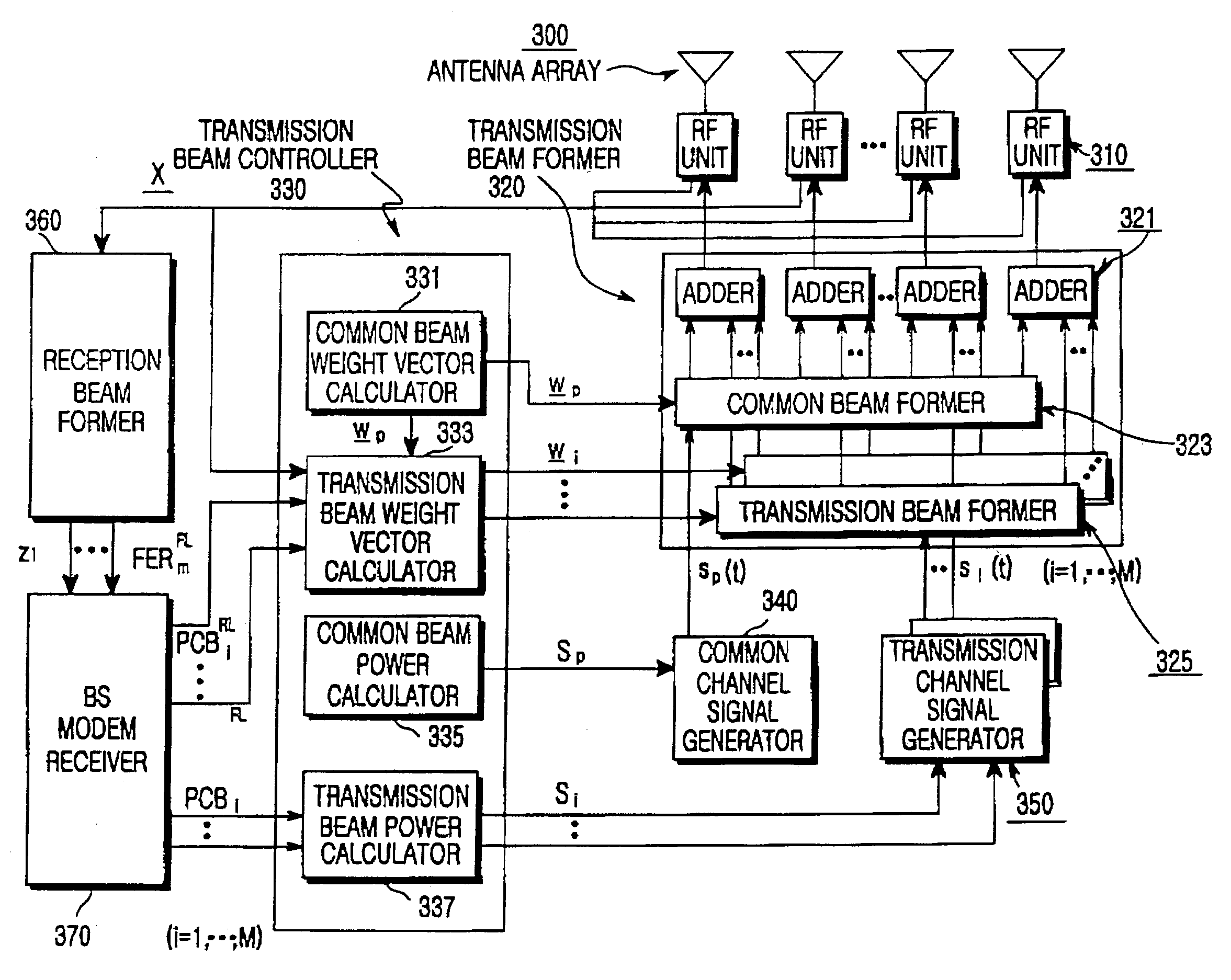
[0030]Several embodiments of the present invention will now be described in detail with reference to the accompanying drawings. In the drawings, the same or similar elements are denoted by the same reference numerals. In the following description, a detailed description of known functions and configurations incorporated herein has been omitted for conciseness.

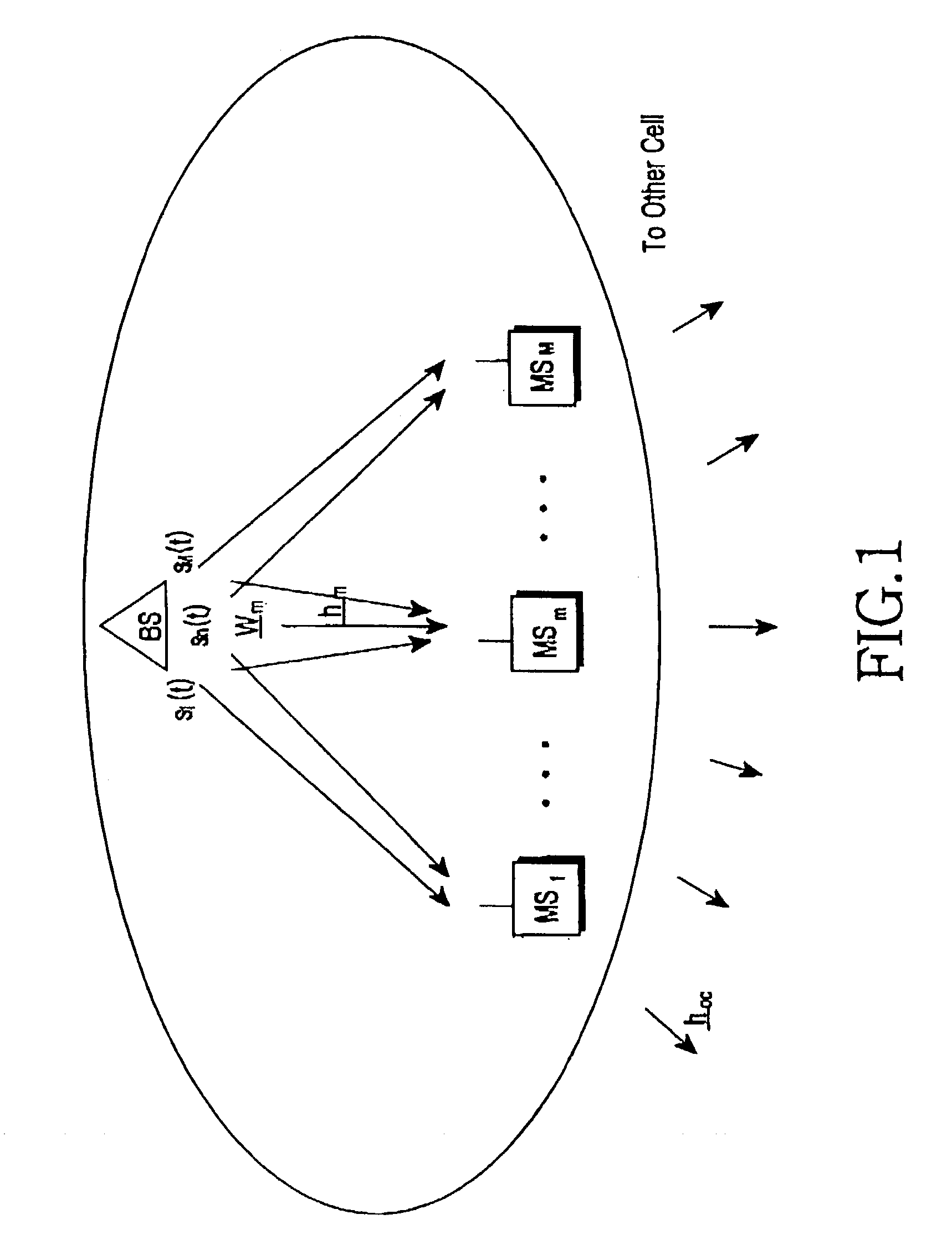
[0031]The embodiments of the present invention will be described with reference to two different cases. The first case provides a method for calculating an optimal transmission weight vector when there is no dedicated pilot channel and only a common pilot channel exists. The second case provides a method for calculating an optimal transmission weight vector when a dedicated pilot channel exists, e.g., the special case described in conjunction with the prior art. Embodiments of the present invention can be generally applied to a current mobile communication system, such as FDMA, TDMA and CDMA. However, for convenience, the embod...


PUM


Abstract

A method and apparatus for a base station including an antenna array calculates a direction of a weight vector of a transmission beam to maximize in-phase component power for a common channel signal in a transmission channel signal for transmission to a mobile station and to minimize a sum of quadrature-phase power component and interference power for other mobile stations inside and outside a cell due to a transmission channel signal for the mobile station.

Description

PRIORITY[0001]This application claims priority under 35 U.S.C. § 119 to an application entitled “Apparatus and Method for Forming Forward Link Transmission Beam of Smart Antenna in a Mobile Communication System” filed in the Korean Intellectual Property Office on May 17, 2002 and assigned Serial No. 2002-27324, the contents of which are incorporated herein by reference.BACKGROUND OF THE INVENTION[0002]1. Field of the Invention[0003]The present invention relates generally to a smart antenna apparatus and method, and in particular, to an apparatus and method for forming forward link transmission beams of a smart antenna in a mobile communication system.[0004]2. Description of the Related Art[0005]In order to meet a rapidly increasing demand for mobile communication and provide various multimedia services to users, there is a great necessity to increase capacity of a forward link. Typically, frequency division multiple access (FDMA) and time division multiple access (TDMA) are used to ...

Claims


Application Information

Patent Timeline
Patent Type & Authority Patents(United States)
IPC IPC(8): H04M1/00H04B1/38H04B7/10G01S3/74H04B1/00H04B7/02H04B7/06H04B7/26H04W16/28
CPCH04W16/28H04B7/0617G01S3/74
Inventor CHUN, BYUNG-JIN
Owner SAMSUNG ELECTRONICS CO LTD
Why Eureka
Try Eureka