
Receiving antenna and wireless power receiving device including the same

a technology of receiving antenna and receiving device, which is applied in the direction of waveguide type devices, loop antennas with ferromagnetic cores, transportation and packaging, etc., can solve the problem of reducing and achieve the effect of increasing the performance of electromagnetic energy focusing of the receiving antenna in the wireless power receiving device, maximizing the wireless power transceiving efficiency, and increasing the guiding effect of the soft magnetic layer

Active Publication Date: 2016-06-02
SCRAMOGE TECH LTD
View PDF6 Cites 79 Cited by
  • Summary
  • Abstract
  • Description
  • Claims
  • Application Information

AI Technical Summary

Benefits of technology

The present invention improves the performance of wireless power receiving devices by using electromagnetic energy focusing. By removing an air layer between the receiving coil and a soft magnetic layer, the guiding effect of the magnetic field is increased, resulting in higher power transmission efficiency. This allows for thin antennas and efficient power transceiving. The invention can be used in various electronic devices and even in applications such as electric cars and subway trains. It also improves reliability and reduces the risk of electrical short.

Problems solved by technology

In that case, an air layer is formed between the receiving coil and the soft magnetic layer, and therefore there may be a problem that guiding effect of a magnetic field of the soft magnetic layer is reduced.

Method used


Image

  • Receiving antenna and wireless power receiving device including the same
  • Receiving antenna and wireless power receiving device including the same
  • Receiving antenna and wireless power receiving device including the same

Examples


Embodiment Construction

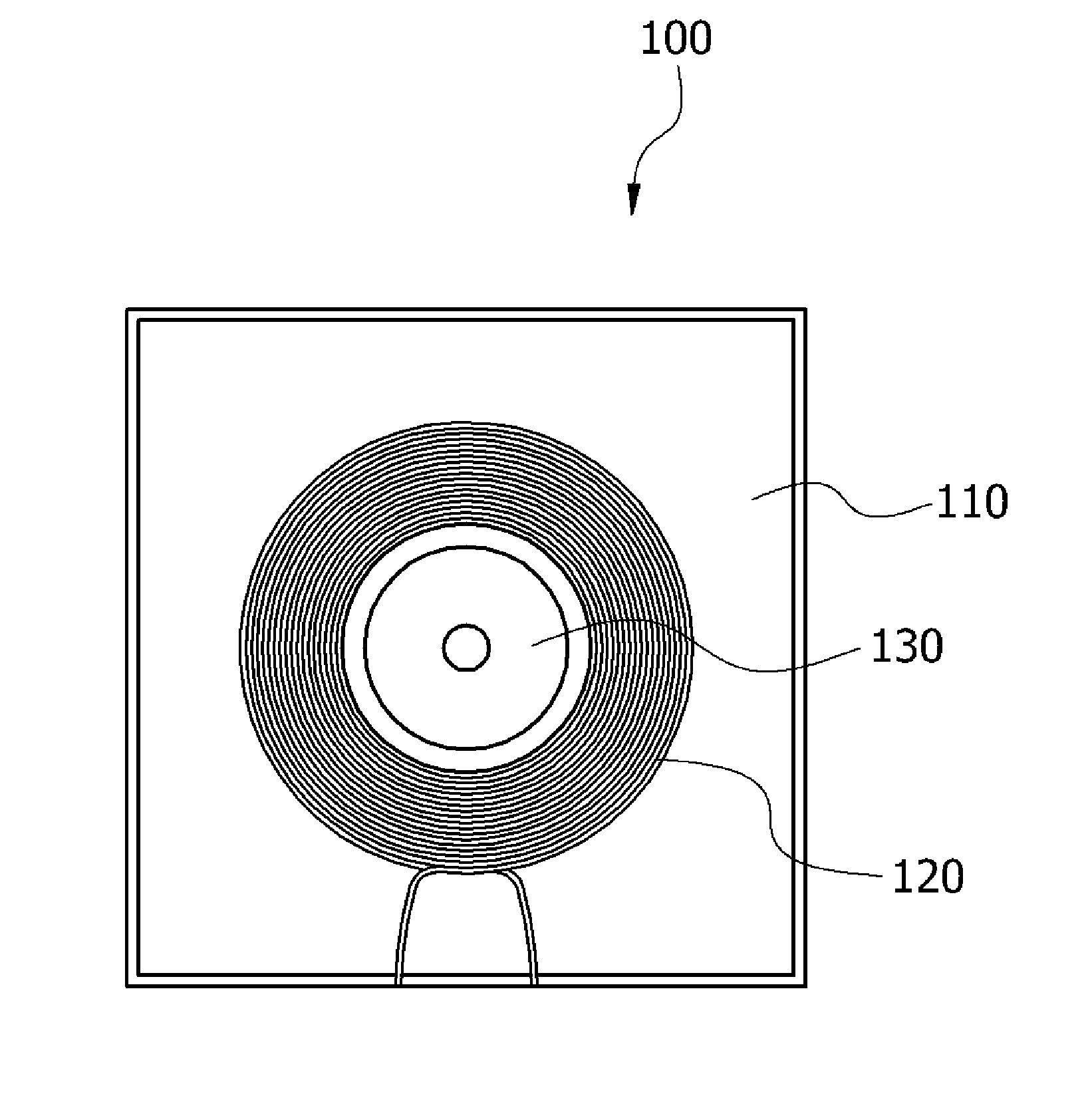
[0027]While the inventive concept is susceptible to various modifications and alternative forms, specific embodiments thereof are shown by way of example in the drawings and will herein be described in detail. It should be understood, however, that there is no intent to limit the inventive concept to the particular forms disclosed, but on the contrary, the inventive concept is to cover all modifications, equivalents, and alternatives falling within the spirit and scope of the inventive concept.

[0028]It will be understood that, although the terms “first,”“second,” etc. may be used herein to describe various components, these components should not be limited by these terms. These terms are only used to distinguish one component from another component. Thus, a first component discussed below could be termed a second component and the second component discussed below could be termed the first component without departing from the teachings of the present inventive concept. The “and / or” i...


PUM


Abstract

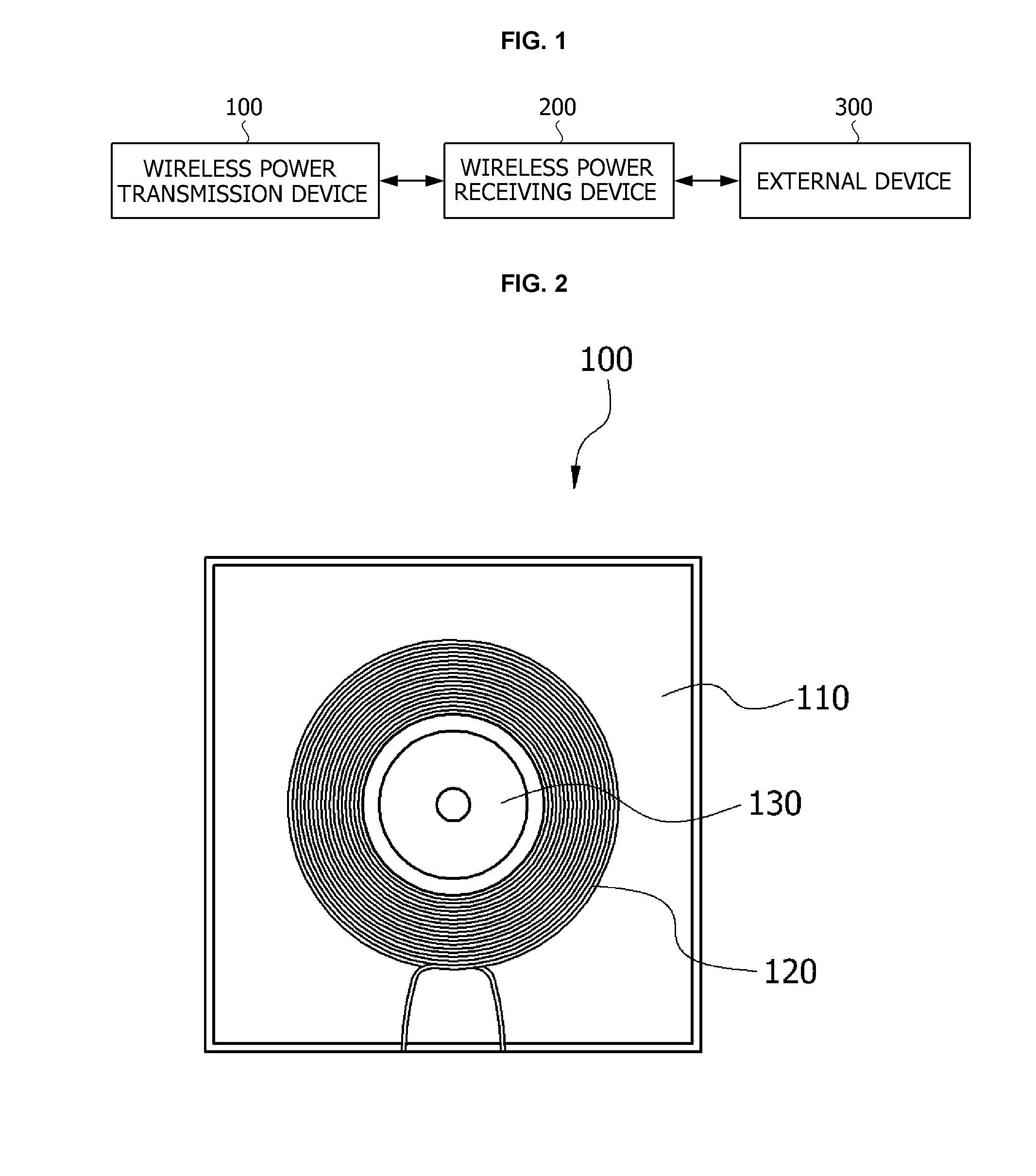
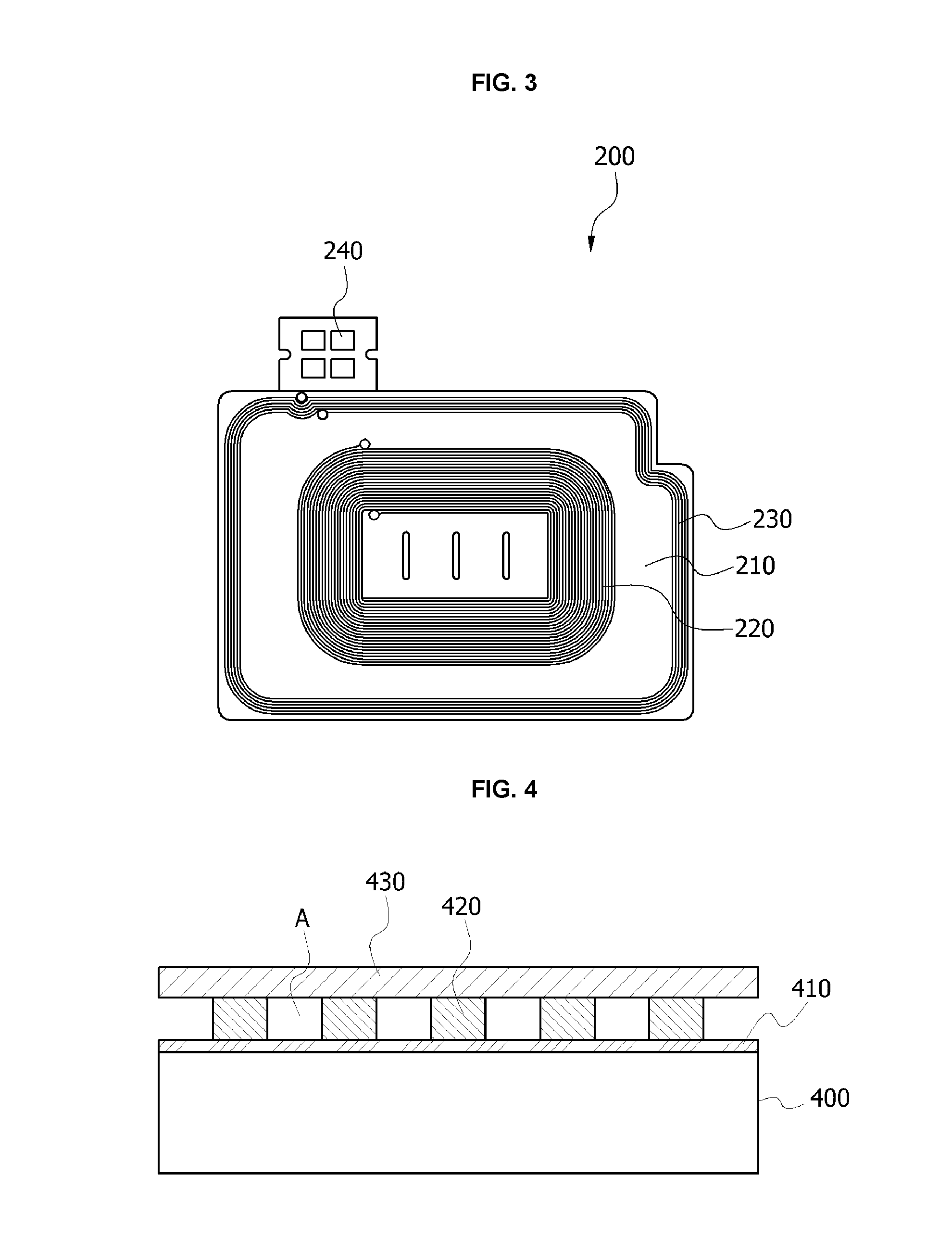
A receiving antenna of a wireless power receiving device wirelessly charging electric power according to an embodiment of the present invention includes a substrate, a soft magnetic layer stacked on the substrate, and a receiving coil configured to receive electromagnetic energy emitted from a wireless power transmission device, wound in parallel with a plane of the soft magnetic layer, and formed inside of the soft magnetic layer, and an insulating layer is formed between the soft magnetic layer and the receiving coil.

Description

TECHNICAL FIELD[0001]The present invention relates to wireless charging, and more particularly, to a receiving antenna for wireless charging and a wireless power receiving device including the same.BACKGROUND ART[0002]According to the development of wireless communication technology, interest in wireless power transceiving technology which provides electric power to electronic devices wirelessly is increasing. The wireless power transceiving technology may be diversely applied to a power supply for household electronic products and for electric cars or subway trains, as well as battery charging of portable terminals.[0003]General wireless power transceiving technology uses a principle of magnetic induction or magnetic resonance. For example, when electrical energy is applied to a transmission antenna of a wireless power transmission device, the transmission antenna may convert the electrical energy into electromagnetic energy and emit the electromagnetic energy to the surroundings. ...

Claims


Application Information

Patent Timeline
Patent Type & Authority Applications(United States)
IPC IPC(8): H01Q7/06H02J7/02
CPCH02J7/025H01Q7/06H02J50/27H02J50/12H02J50/70H04B5/79H01Q1/38H04B5/26H02J50/10H02J50/20
Inventor BAE, SEOKCHOI, DONCHULHYUN, SOON YOUNG
Owner SCRAMOGE TECH LTD
Learn More