
Adjustable shower head

a shower head and adjustable technology, applied in the field of shower heads, can solve the problems of water seeping under the bath tub, damage by user pulling, and undesirable to install a longer hose, and achieve the effect of effectively extending and retracting the shower head

Inactive Publication Date: 2006-06-27
STOUT JR LEONARD L
View PDF7 Cites 9 Cited by
  • Summary
  • Abstract
  • Description
  • Claims
  • Application Information

AI Technical Summary

Benefits of technology

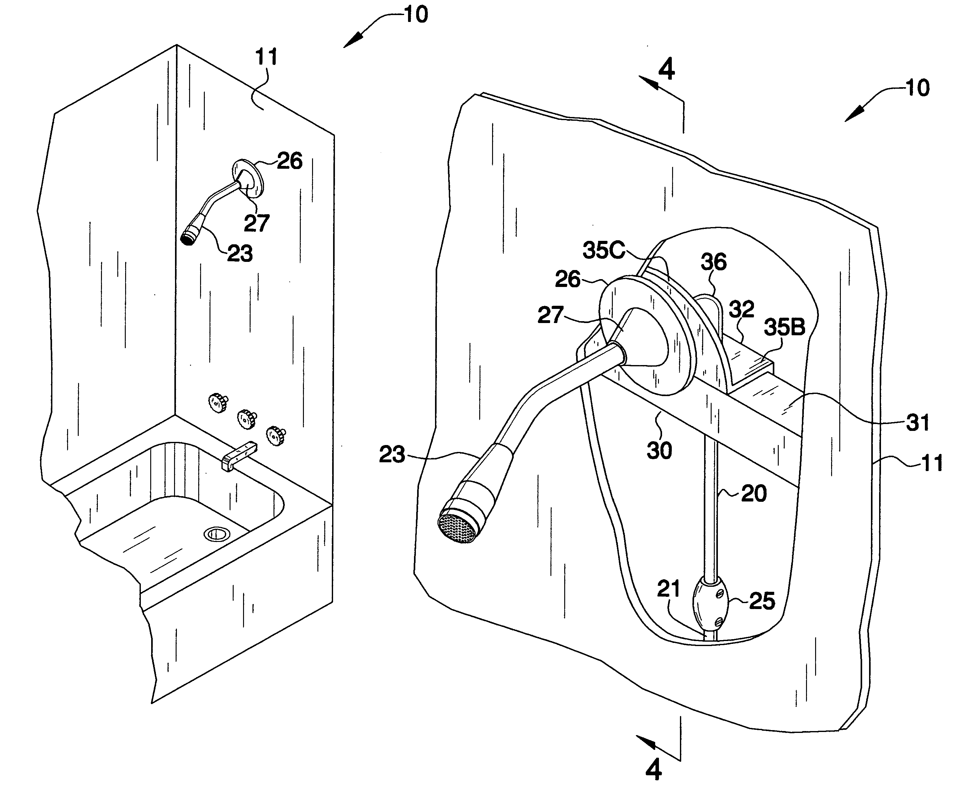
"The present invention provides an adjustable shower head that allows a user to more effectively extend and retract the shower head from a rested position. The shower head assembly includes a flexible conduit, a shower head, a weight member, a support beam, a support bracket, and a non-linear sleeve. The flexible conduit has one end connected to a water supply source and is in direct fluid communication with the shower head. The shower head can be selectively adapted between extended and retracted positions. The weight member helps to counteract the user's lateral force when extracting the shower head from the rested position. The support beam is attached to the shower wall and has a monolithically formed funnel portion for guiding the conduit. The support bracket is securely attached to the support beam and has a monolithically formed first, second, and third walls for conforming to the support beam sides and the shower wall. The non-linear sleeve is directed to direct the conduit along vertical and horizontal paths during operating conditions and minimize frictional contact with the support bracket and the support beam. These features make the shower head assembly more convenient and efficient for users."

Problems solved by technology

The hole often leads to water seeping under the bath tub.
Furthermore, these drawbacks (difficulty of storage and problems with dirt) make it undesirable to install a longer hose, even though a longer hose would often be convenient when the shower head is in use.
As a result of shower hoses not being long enough, they are often damaged by the user pulling on them.

Method used


Image

  • Adjustable shower head
  • Adjustable shower head
  • Adjustable shower head

Examples


Embodiment Construction

[0029]The present invention will now be described more fully hereinafter with reference to the accompanying drawings, in which a preferred embodiment of the invention is shown. This invention may, however, be embodied in many different forms and should not be construed as limited to the embodiment set forth herein. Rather, this embodiment is provided so that this application will be thorough and complete, and will fully convey the true scope of the invention to those skilled in the art. Like numbers refer to like elements throughout the figures.

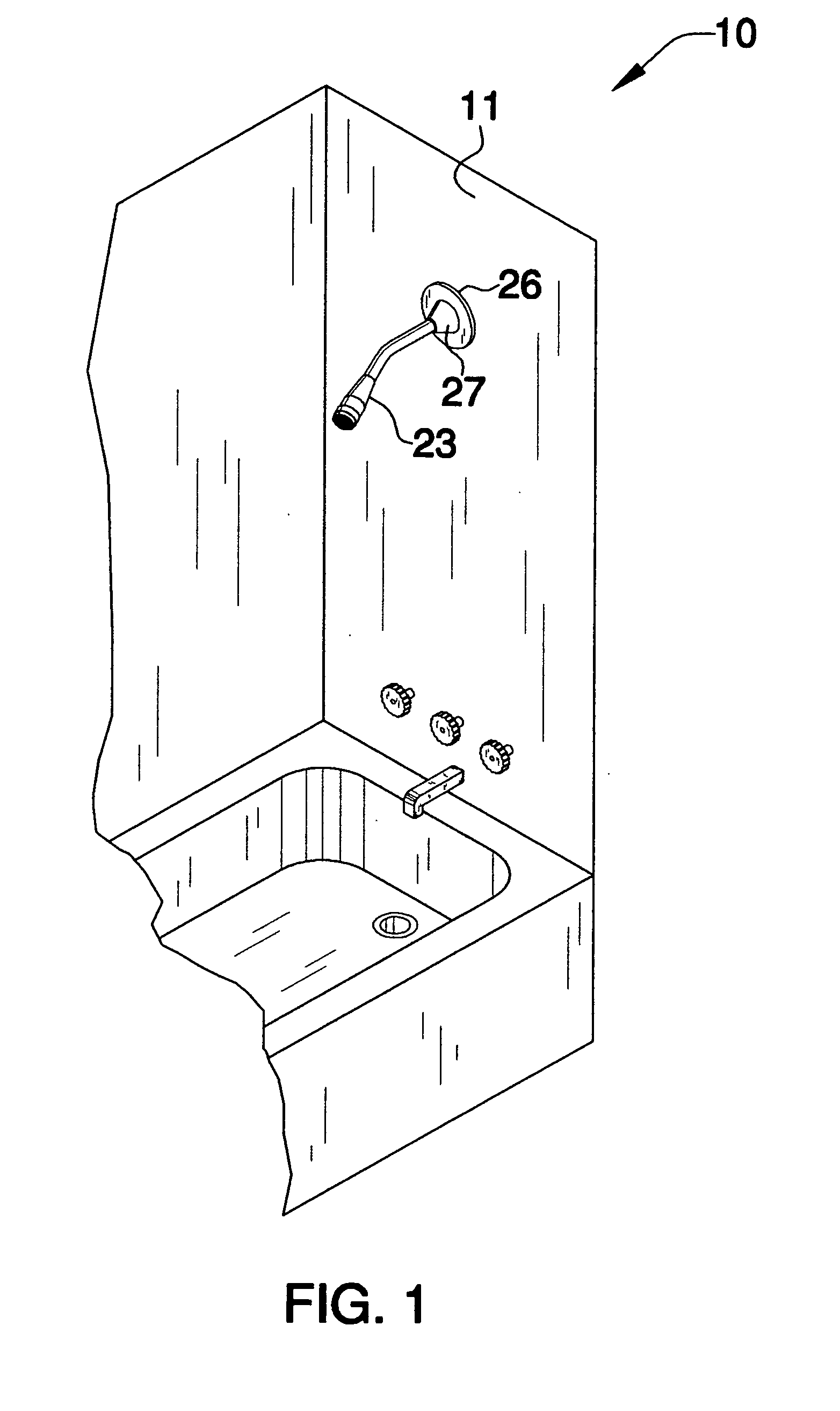
[0030]The assembly of this invention is referred to generally in FIGS. 1–6 by the reference numeral 10 and is intended to provide an adjustable shower head. It should be understood that the assembly 10 may be used to extend many different types of shower heads and should not be limited in use to only extending conventional shower heads.

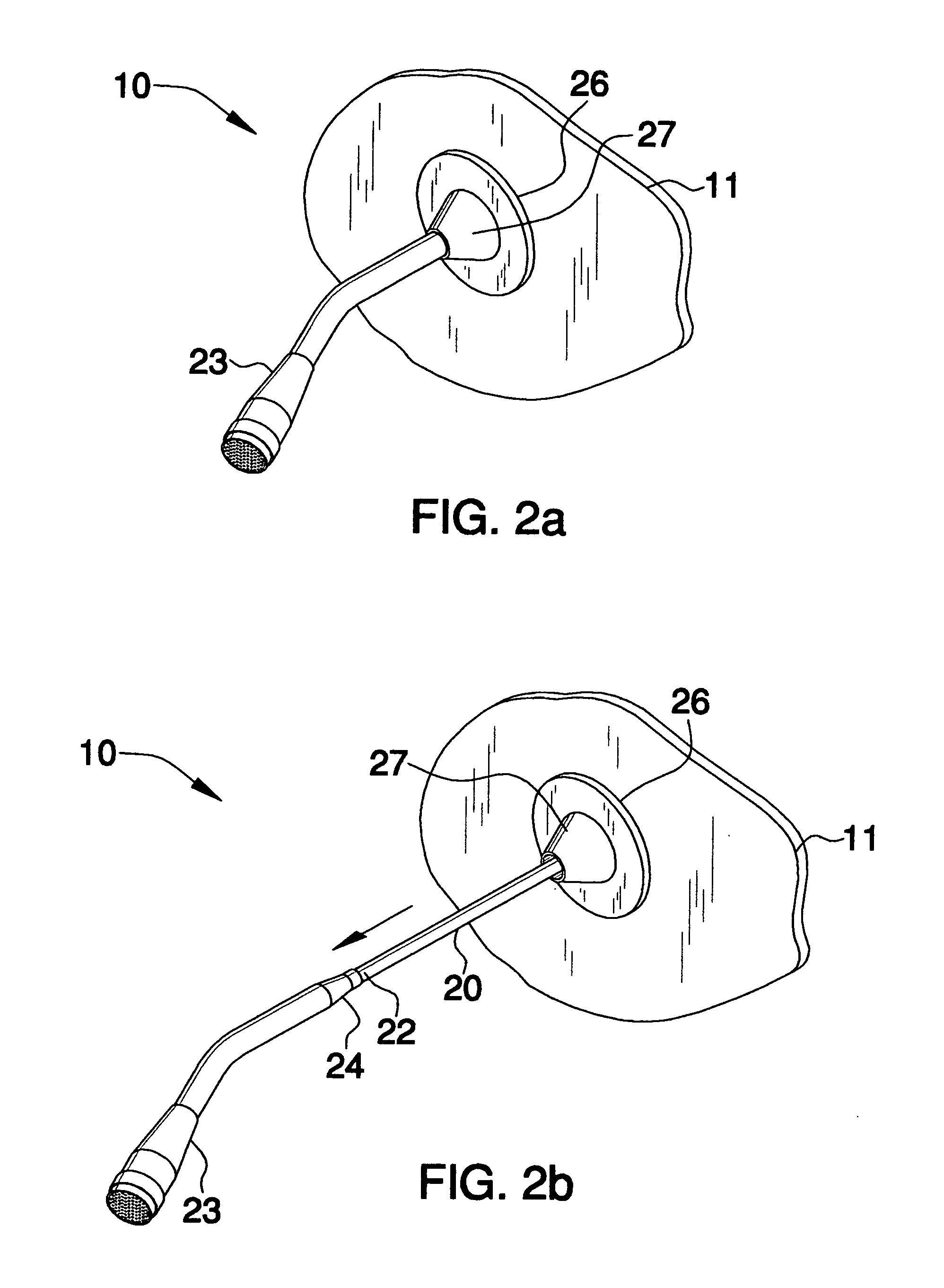
[0031]Referring initially to FIGS. 2b and 3, the assembly 10 includes an elongated and flexible conduit 20 t...


PUM


Abstract

An assembly includes a conduit that has one end portion engaged with a water supply source and another end portion situated to an exterior of a shower wall. A shower head that has a tapered end portion is conjoined to another end portion. A wall flange, fastened to an exterior of the shower wall, has a funnel portion protruding orthogonally away therefrom. A support beam, positioned orthogonal to a longitudinal axis and attached to the rear of the shower wall, has a pair of sides disposed orthogonal to each other. A support bracket, fastened to one side, has an aperture formed therein for guiding the conduit therethrough. The wall flange has an aperture registered with the support bracket aperture for guiding the conduit therealong. A sleeve, fastened to the support bracket and the support beam, has first and second end portions directing the conduit vertically and horizontally therealong.

Description

CROSS REFERENCE TO RELATED APPLICATIONS[0001]Not Applicable.STATEMENT REGARDING FEDERALLY SPONSORED RESEARCH OR DEVELOPMENT[0002]Not Applicable.REFERENCE TO A MICROFICHE APPENDIX[0003]Not Applicable.BACKGROUND OF THE INVENTION[0004]1. Technical Field[0005]This invention relates to shower heads and, more particularly, to an adjustable shower head for assisting a user to more effectively extend and retract the shower head from a rested position.[0006]2. Prior Art[0007]The use of adjustable shower heads is known in the prior art. More specifically, adjustable shower heads heretofore devised and utilized are known to consist basically of familiar, expected and obvious structural configurations, notwithstanding the myriad of designs encompassed by the crowded prior art which have been developed for the fulfillment of countless objectives and requirements.[0008]Adjustable shower head assemblies are conventionally constituted by a hose which may be in the form of a flexible tube protected ...

Claims


Application Information

Patent Timeline
Patent Type & Authority Patents(United States)
IPC IPC(8): A47K3/022A47K3/34A47K3/36
CPCA47K3/28B05B15/066E03C1/042E03C1/0408E03C2001/0415B05B15/652
Inventor STOUT, JR., LEONARD L.
Owner STOUT JR LEONARD L
Learn More