Apparatus and method for droplet steering

a technology of apparatus and droplets, applied in the direction of electric spraying apparatus, burners, printing, etc., can solve the problem of longer flight times of ejected droplets

Inactive Publication Date: 2006-08-01
LABCYTE
View PDF139 Cites 4 Cited by
  • Summary
  • Abstract
  • Description
  • Claims
  • Application Information

AI Technical Summary

Benefits of technology

[0011]An apparatus and method for steering droplets, i.e., correcting or altering the trajectory of droplets moving through free space, by utilizing directed fluid flow is disclosed herein. Generally, a throated structure preferably comprising a nozzle defining a throat may have an inlet or entrance port and a preferably smaller outlet or exit port. A venturi structure may also be used in which case the inlet or entrance port may open into a nozzle which converges to a narrower throat and reopens or diverges into a larger outlet or exit port. Use of a venturi structure, however, may result in longer flight times for the ejected droplets prior to reaching the targeting medium.
[0013]A droplet ejected from the surface of a liquid will typically have a first trajectory or path. The liquid is preferably contained in a well or reservoir disposed below the nozzle. To prevent overheating of the liquid within the reservoir during droplet ejection, the temperature of the wellplate may be controlled actively, e.g., through conductive thermal heating or cooling, or the droplet generator may be used indirectly to control the temperature of each of the wells during droplet ejection. If the trajectory angle of the droplet relative to a centerline of the inlet nozzle is relatively small, i.e., less than a few tenths of a degree off normal, the droplet may pass through the outlet and on towards a target with an acceptable degree of accuracy. If the trajectory angle of the droplet is relatively large, i.e., greater than a few degrees and up to about ±22.5°, the droplet may be considered as being off target.
[0014]As the droplet enters the inlet off-angle and as it advances further up into the structure, the droplet is introduced to the high velocity fluid stream at the perimeter of the interior walls of the nozzle. The fluid stream accordingly steers or redirects the momentum of the droplet such that it obtains a second or corrected trajectory which is closer to about 0° off-axis. The fluid stream at the connecting deviated fluid flow channel is preferably drawn away from the centerline of the nozzle and although the droplet may be subjected to the fluid flow from the connecting deviated fluid flow channel, the droplet has mass and velocity properties that constrain its ability to turn at right or acute angles when traveling at a velocity, thus the droplet is allowed to emerge cleanly from the outlet with high positional accuracy. Throated structure may correct for droplet angles of up to about ±22.5°, but more accurate trajectory or correction results may be obtained when the droplet angles are between about 0°-15° off-axis.
[0015]To facilitate efficient fluid flow through the throated structure, the throat is preferably surrounded by a wall having a cross-sectional elliptical shape. That is, the cross-sectional profile of the wall taken in a plane that is parallel to or includes the axis of the nozzle preferably follows a partial elliptical shape. The exit channels which draw the fluid away from the centerline of the throat may also have elliptically shaped paths to help maintain smooth laminar flow throughout the structure. It also helps to bring the fluid flow parallel to the centerline as well as maintaining a smooth transition for the exit flow as well as maintaining an equal exit flow on the throat diameter. This in turn may help to efficiently and effectively eject droplets through the structure.
[0017]Additionally, an electrically chargeable member, e.g., a pin, may be positioned in apposition to the outlet to polarize the droplets during their travel towards the target. Polarizing the droplets helps to influence the droplet trajectory as the droplets are drawn towards the chargeable member for more accurate droplet deposition. Additionally, well inserts for controlling the ejection surface of the pool of source fluid from which the droplets are ejected may also be used in conjunction with the throated structure. Furthermore, various manifold devices may be used to efficiently channel the fluid through the system.
[0020]Another variation may include using a well mask having a variable orifice diameter defined therein for use either with a single throated structure design, or using a well mask with multiple orifices for use with a lid assembly having multiple throats defined therein and placed over a wellplate. Such a well mask may be used particularly with wellplates having relatively large diameter wells, i.e., wells with diameters measuring 4.5 mm or greater, to emulate a smaller diameter well to aid in fluid flow efficiency.

Problems solved by technology

Use of a venturi structure, however, may result in longer flight times for the ejected droplets prior to reaching the targeting medium.

Method used


Image

  • Apparatus and method for droplet steering
  • Apparatus and method for droplet steering
  • Apparatus and method for droplet steering

Examples


Embodiment Construction

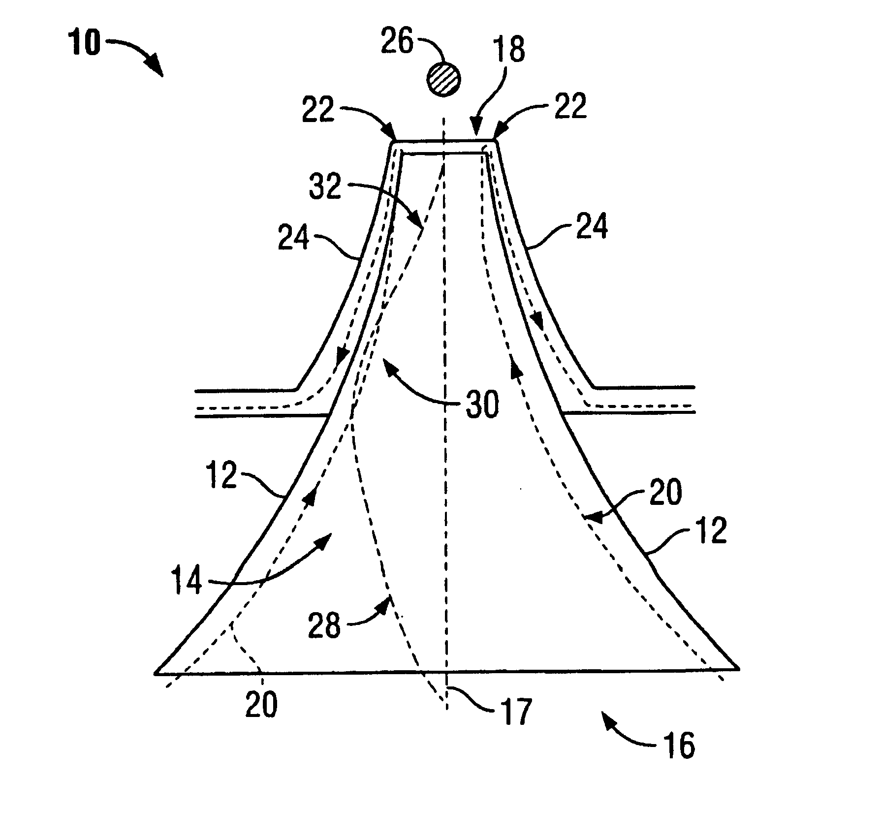
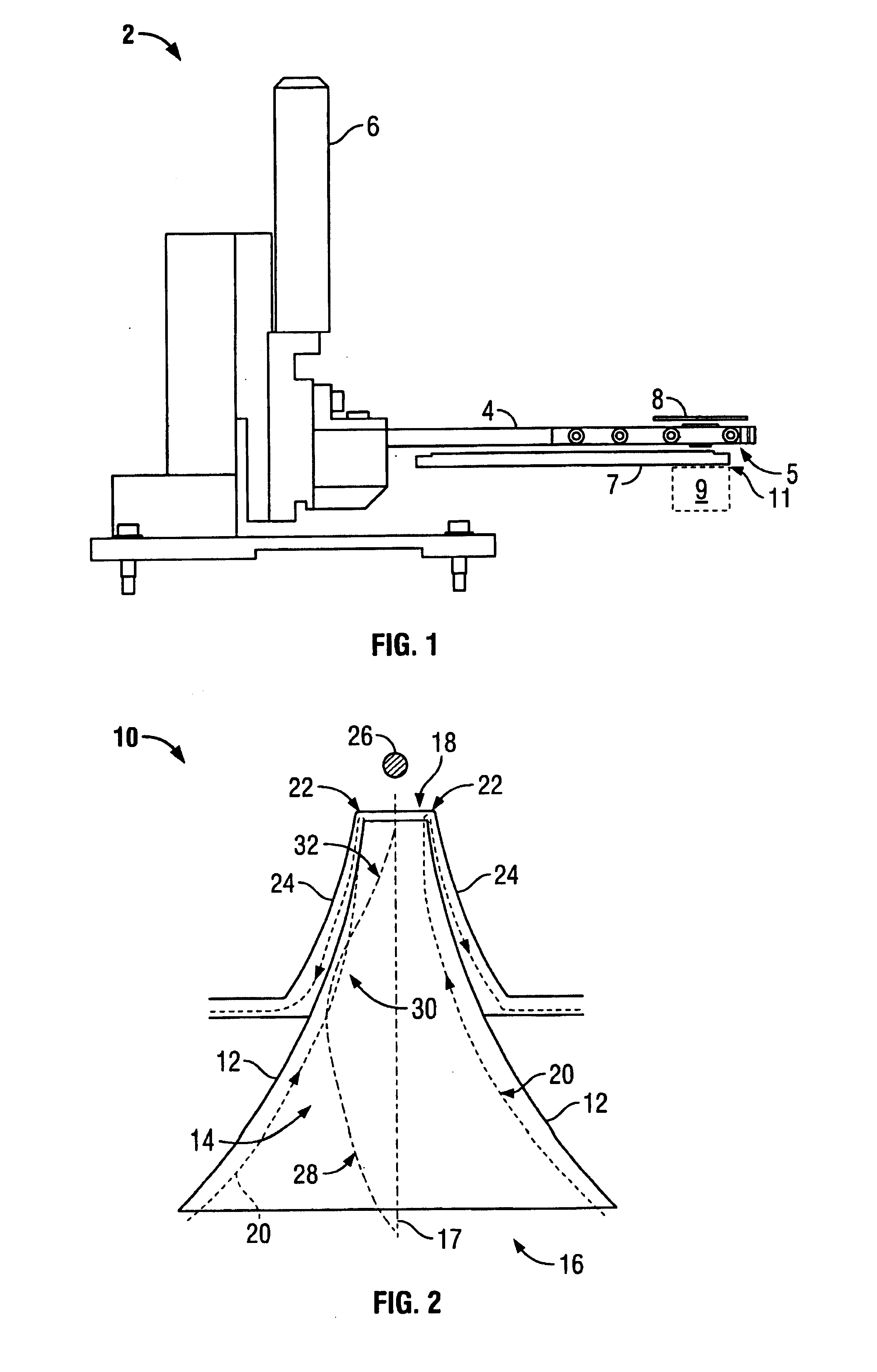
[0048]An apparatus and method for droplet steering, i.e., correcting or altering the trajectory of a droplet moving through free space, by utilizing directed fluid flow, e.g., gas flow, is disclosed herein. A representative schematic diagram of a non-contact fluid transfer system 2 is shown in FIG. 1. As seen, support arm 4 extends from a platform which may be manipulated via, e.g., z-axis adjustment assembly 6, over wellplate 7. Wellplate 7 may contain a single well or reservoir or it may contain numerous wells. Wellplate 7 may be a microwell in a conventional microtiter plate, which are made with a number of wells, e.g., 24, 96, 384, 1536, 3456, 6912, or any number combination source of wells. A droplet steering assembly 5, which operates according to the principles disclosed herein, is preferably located near the end of support arm 4 and over droplet generator 9. Steering assembly 5 is also preferably disposed beneath or adjacent to a targeting medium 8. As applied throughout, an...


PUM


Abstract

An apparatus and method for droplet steering is disclosed herein. A throated structure having a nozzle defines a converging throat with an inlet and an outlet and a vectored fluid stream directed therethrough. The fluid stream is driven through the system via a vacuum pump. As the fluid approaches the outlet, its velocity increases and is drawn away from the nozzle through a connecting channel. As a droplet is ejected from a liquid therebelow, it will have a first trajectory until it is introduced to the high velocity fluid stream at the perimeter of the interior walls of the nozzle. The fluid accordingly steers the momentum of the droplet such that it obtains a second or corrected trajectory. Alternative variations include an electrically chargeable member, e.g., a pin, positionable to be in apposition to the outlet and capillary tubes for controlling the ejection surface of the pool of source fluid.

Description

CROSS-REFERENCE TO RELATED APPLICATIONS[0001]This application is a continuation-in-part of U.S. patent application Ser. No. 10 / 006,489 filed Dec. 6, 2001, which claims the benefit of priority of U.S. Provisional Patent Application Ser. No. 60 / 348,429 filed Oct. 29, 2001, each of which is incorporated herein by reference in its entirety.FIELD OF THE INVENTION[0002]The invention relates generally to the control of a trajectory of a fluid moving in free space. More particularly, the invention relates to apparatus and methods of trajectory correction of liquid droplets moving through free space via directed fluid flows and electrostatic devices.BACKGROUND OF THE INVENTION[0003]Various technologies have been developed utilizing techniques in which fluids are ejected from a reservoir by focused acoustic energy. An example of such technology is typically referred to as acoustic ink deposition which uses focused acoustic energy to eject droplets of a fluid, such as ink, from the free surfac...

Claims


Application Information

Patent Timeline
Patent Type & Authority Patents(United States)
IPC IPC(8): B05B1/28B05B1/08B41J2/14
CPCB41J2/14008
Inventor WILLIAMS, ROGER O.VAN TUYL, MICHAELFORBUSH, MICHAEL
Owner LABCYTE
Why Eureka
Try Eureka