Articulating inlet for airbreathing extended range projectiles and missiles

a technology of projectiles and inlets, which is applied in the direction of self-propelled projectiles, projectiles, weapons, etc., can solve the problems of significant space shortages within the projectile, insufficient range of conventional projectiles, and insufficient performance of projectiles, so as to achieve optimal flight time, shorten the range, and the effect of long rang

Pending Publication Date: 2022-06-02
RAYTHEON CO
View PDF5 Cites 0 Cited by
  • Summary
  • Abstract
  • Description
  • Claims
  • Application Information

AI Technical Summary

Benefits of technology

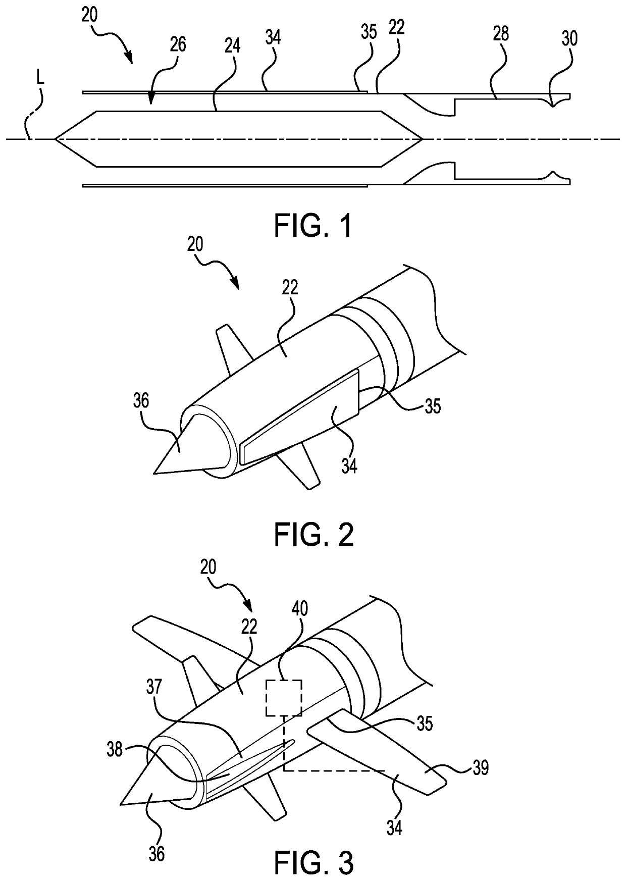
[0006]The present application provides a projectile that uses a wing structure to form both an inlet that intakes air for combustion by a propulsion system of the projectile during an initial range of flight and a lift surface for the projectile after the propulsion engine of the propulsion system burns out. In contrast to conventional projectiles which include a ramjet-only variant that provides an optimal time of flight to the target but a shorter range, and a wing-only variant that provides a longer range but an undesirable long flight time, the wing structure that acts as both the inlet and the lift surface enables both a long range and an optimal time of flight to the target.

Problems solved by technology

Projectiles, such as missiles typically have space constraints such that the space must be balanced for both guidance electronics and a propulsion system.
In an exemplary ramjet-type projectile, a solid-fuel ramjet propulsion system that uses airflow ducts may lead to significant space shortages within the projectile.
However, conventional projectiles may be deficient in maximizing the range, which relies on either reducing the drag in and around the inlets or increasing the lift of the airframe for the projectile.
However, this solution is deficient in that it does not address the source of drag created by the inlets of the air breathing propulsion system after the ramjet fuel is expended, such that the projectile may be subject to inadequate performance.

Method used


Image

  • Articulating inlet for airbreathing extended range projectiles and missiles
  • Articulating inlet for airbreathing extended range projectiles and missiles
  • Articulating inlet for airbreathing extended range projectiles and missiles

Examples


Embodiment Construction

[0049]The principles described herein have application for use with projectiles, such as artillery rounds or missiles. The projectiles may be implemented in various applications, such as in defense applications or in any other suitable projectile applications including non-military applications. The principles described herein may be implemented in any suitable projectile, such as a solid-fuel ramjet, a liquid-fuel ramjet, or a ducted rocket. Projectile launch systems, such as tube or gun launch systems may also be used in conjunction with the projectiles and principles described herein.

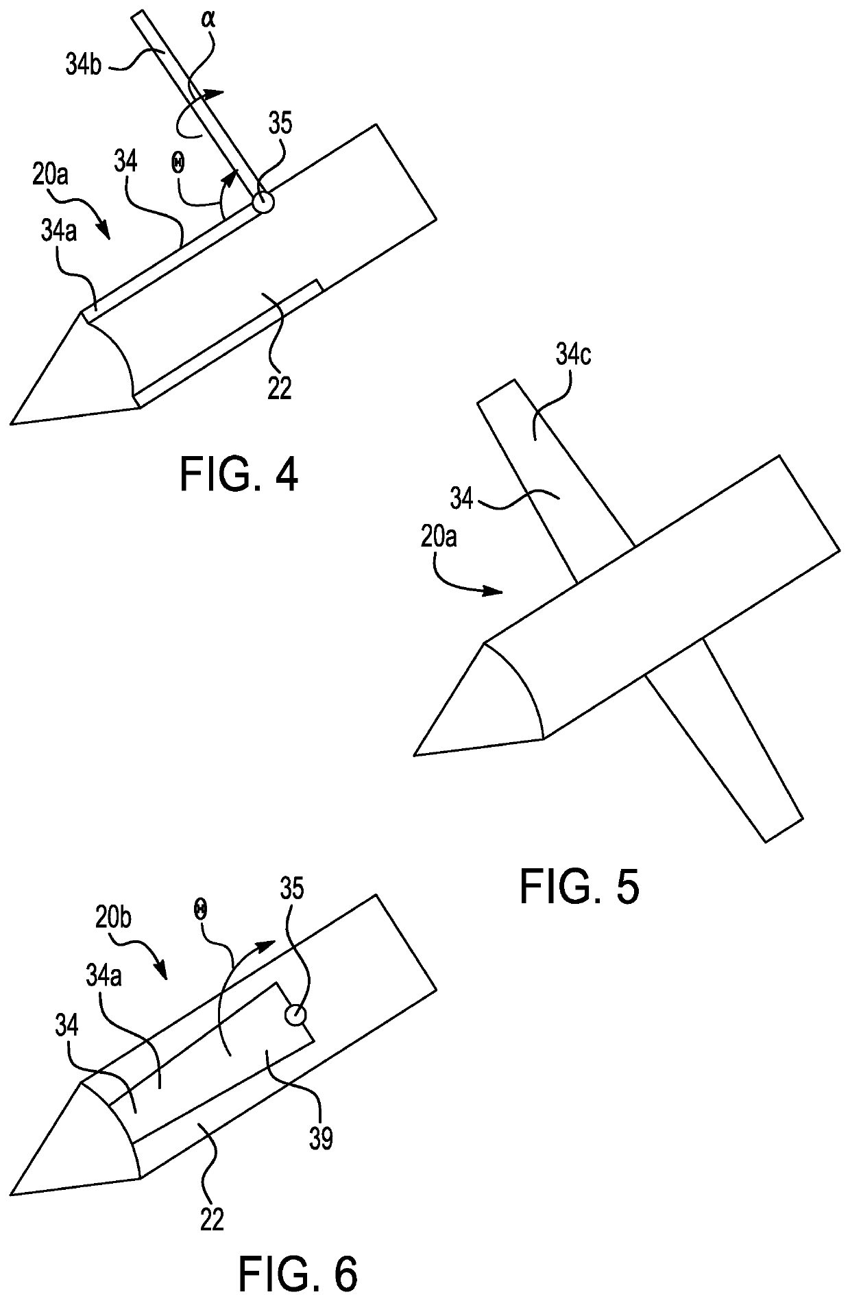
[0050]Referring first to FIG. 1, a schematic drawing of a projectile 20 is shown. The projectile 20 may be a solid-fuel ramjet, a liquid-fuel ramjet, a ducted rocket, or any other suitable projectile. For example, the projectile 20 may be a ramjet that includes a propulsion body section 22 having a propulsion system and engine for the ramjet. The propulsion body section 22 houses various components o...


PUM


Abstract

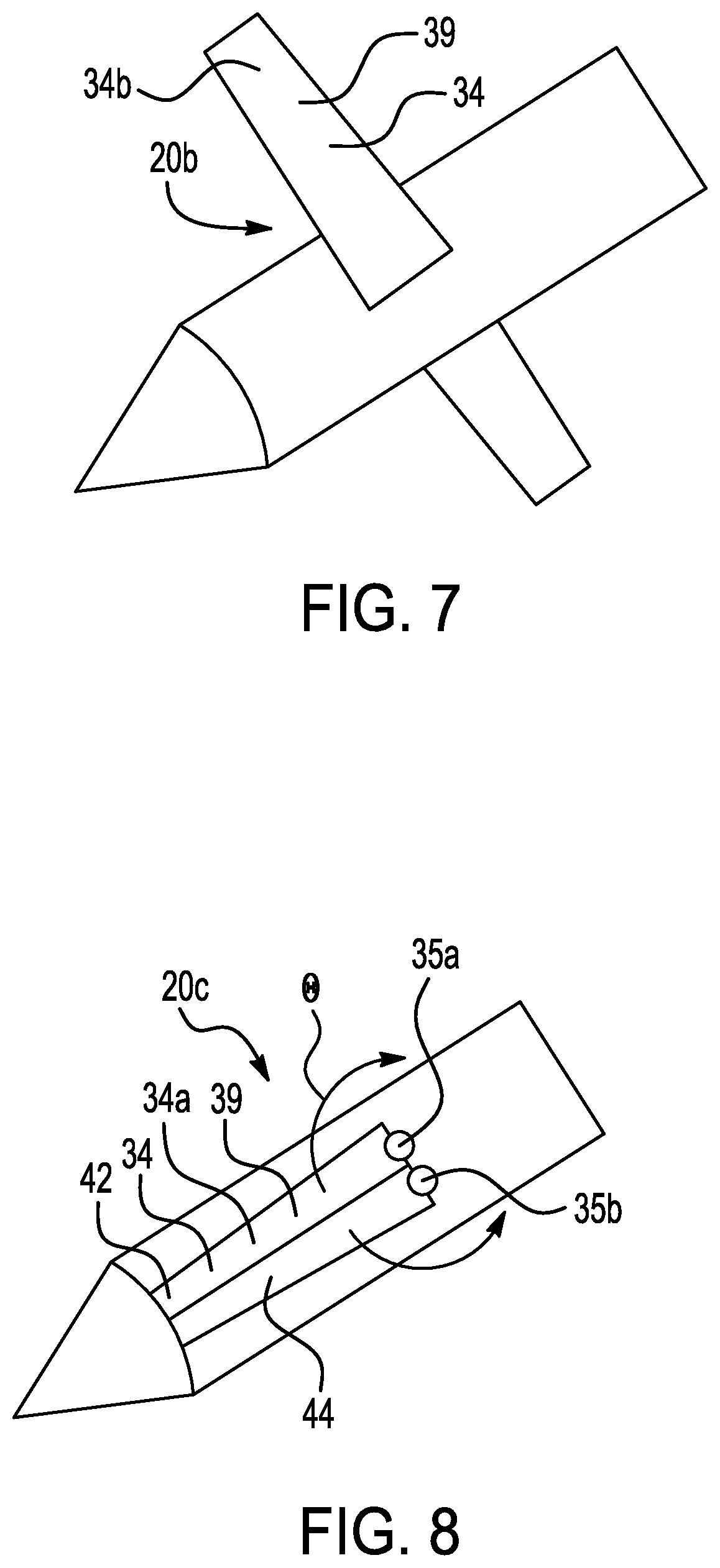
A projectile includes a wing structure to form both an inlet that intakes air for combustion by a propulsion system of the projectile during an initial range of flight, and a lift surface for the projectile after the propulsion engine of the propulsion system burns out. The wing structure acts as both the inlet and the lift surface to enable both a long range and an optimal time of flight for the projectile to the target. The wing structure includes at least one wing that is movable from a folded position, in which the wing extends along a propulsion body section of the projectile to define the inlet, to a deployed position, in which the wing extends outwardly from the propulsion body section to form the lift surface. Any number of wings may be provided and the wings may be simultaneously deployed or sequentially deployed depending on the application.

Description

RELATED APPLICATIONS[0001]This application claims the benefit of U.S. Provisional Application No. 63 / 119,692 filed Dec. 1, 2020, which is hereby incorporated herein by reference in its entirety.GOVERNMENT LICENSE RIGHTS[0002]This disclosure was made with Government support under contract number DOTC-19-01-INIT0845, awarded by the Department of Defense. The Government has certain rights in the disclosure.FIELD OF DISCLOSURE[0003]The disclosure relates to inlets for projectiles and missiles.DESCRIPTION OF RELATED ART[0004]Projectiles, such as missiles typically have space constraints such that the space must be balanced for both guidance electronics and a propulsion system. In an exemplary ramjet-type projectile, a solid-fuel ramjet propulsion system that uses airflow ducts may lead to significant space shortages within the projectile. Due to the volume limitations of the standard space provided in the projectile that is shared by the ramjet propulsion system, seeker hardware and proc...

Claims


Application Information

Patent Timeline
Patent Type & Authority Applications(United States)
IPC IPC(8): F42B10/14F42B15/10
CPCF42B10/14F42B15/105F42B15/10
Inventor LOTTI, ANDREW J.BURKE, SHAWN P.MESSITT, DONALD G.JONES, JAYLAN S.
Owner RAYTHEON CO
Why Eureka
Try Eureka