Unmanned aerial vehicle

A technology of unmanned aerial vehicle and machine arm, which is applied in the field of unmanned aerial vehicles, which can solve the problems of troublesome storage, many folding steps of the whole machine, and heavy structural weight of the whole machine, and achieve long flight endurance, wide installation space and fast storage speed Effect

Pending Publication Date: 2020-09-15
SZ DJI TECH CO LTD
View PDF5 Cites 0 Cited by
  • Summary
  • Abstract
  • Description
  • Claims
  • Application Information

AI Technical Summary

Problems solved by technology

According to experience, it is found that the antenna basically needs to be placed on the outermost periphery of the unmanned aerial vehicle in order to work reliably. In the existing unmanned aerial vehicle, the propeller and the motor that provides power for it are connected to the central body through the motor mount and the arm. The antenna is arranged in The bottom of the motor, however, the antenna may be blocked during flight, affecting its normal operation
Although there is a solution to the problem of antenna occlusion by configuring additional antenna brackets, it will lead to a larger structural weight of the whole machine, and a higher proportion of structural weight, which will directly affect the endurance of the unmanned aerial vehicle and cause the whole machine to fold. Lots of steps, troublesome storage

Method used


Image

  • Unmanned aerial vehicle
  • Unmanned aerial vehicle
  • Unmanned aerial vehicle

Examples


Embodiment Construction

[0109] In order to better understand the above-mentioned purpose, features and advantages of the present application, the present application will be further described in detail below in conjunction with the accompanying drawings and specific embodiments. It should be noted that, in the case of no conflict, the embodiments of the present application and the features in the embodiments can be combined with each other.

[0110] In the following description, many specific details are set forth in order to fully understand the application, but the application can also be implemented in other ways different from those described here, therefore, the protection scope of the application is not limited by the specific details disclosed below. EXAMPLE LIMITATIONS.

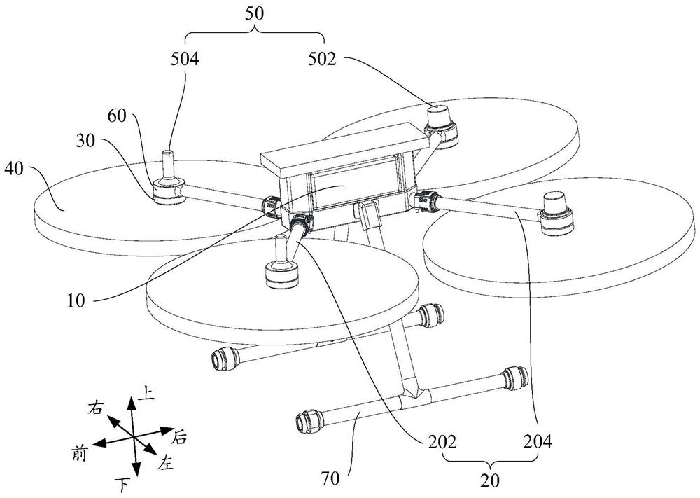
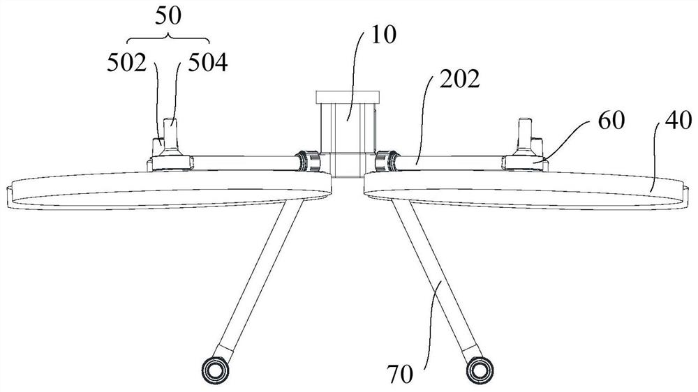
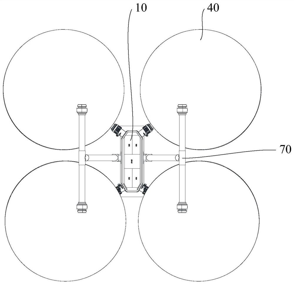
[0111] Refer below Figure 1 to Figure 3 An unmanned aerial vehicle according to some embodiments of the application is described.

[0112] Such as figure 1 As shown, the embodiment of one aspect of the present applicatio...


PUM


Abstract

The invention provides an unmanned aerial vehicle which comprises a center body, a plurality of vehicle arms, a plurality of motors, a plurality of propellers and a plurality of antennas, the vehiclearms are connected with the center body, a motor mounting base is arranged at the end, away from the center body, of each vehicle arm, and each motor mounting base comprises a top and a bottom opposite to the top; the plurality of motors are respectively mounted on the motor mounting seats of the plurality of vehicle arms; the propellers are connected with the motors respectively, and the motors are used for driving the propellers to rotate so as to provide flying power for the unmanned aerial vehicle. The plurality of antennas are respectively arranged on motor mounting bases of at least twovehicle arms in the plurality of vehicle arms, the antennas are located at the tops of the motor mounting bases, the propellers are located at the lower positions relative to the motor mounting bases,and the antennas are located at the upper positions relative to the motor mounting bases. The unmanned aerial vehicle provided by the embodiment of the invention can ensure that the mounting space ofthe antenna is wide, the flight duration is longer, the folding steps are fewer, and the storage speed is higher.

Description

technical field [0001] This application relates to unmanned remote control devices, and in particular, to two types of unmanned aerial vehicles. Background technique [0002] UAVs need to be equipped with structures such as antennas to achieve related functions, such as communication antennas and positioning antennas, which are used to communicate with the remote control device and locate the current position of the UAV. According to experience, it is found that the antenna basically needs to be placed on the outermost periphery of the unmanned aerial vehicle in order to work reliably. In the existing unmanned aerial vehicle, the propeller and the motor that provides power for it are connected to the central body through the motor mount and the arm. The antenna is arranged in The bottom of the motor, however, the antenna may be blocked during the flight, affecting its normal operation. Although there is a solution to the problem of antenna occlusion by configuring additiona...

Claims


Application Information

Patent Timeline
Patent Type & Authority Applications(China)
IPC IPC(8): B64C39/02B64C1/36H01Q1/28B64C1/06B64C27/14B64D27/24B64D27/26
CPCB64C39/024B64C1/36H01Q1/285B64C1/063B64C27/14B64D27/24B64D27/26B64U30/20H01Q1/28B64C2025/325B64C25/52B64U10/13B64U50/19
Inventor 丘力
Owner SZ DJI TECH CO LTD
Why Eureka
Try Eureka