Conservation plant pot

Inactive Publication Date: 2008-12-11
JUNG MAN YOUNG
View PDF5 Cites 4 Cited by
  • Summary
  • Abstract
  • Description
  • Claims
  • Application Information

AI Technical Summary

Benefits of technology

[0008]A plant pot according to the present invention normally operates in a group of modular components although in its singular form the pot provides a unique advantage of controlling water to protect the plant from over watering. The pot part can be made of plastic or ceramic.

Problems solved by technology

However, as the national drought stricken and water conservation becomes the state of problem, there is an urgent need for an advanced approach to draw an excess potting water before it may be undesirably overflowing or over saturate the pot soil.

Method used


Image

  • Conservation plant pot
  • Conservation plant pot
  • Conservation plant pot

Examples


Embodiment Construction

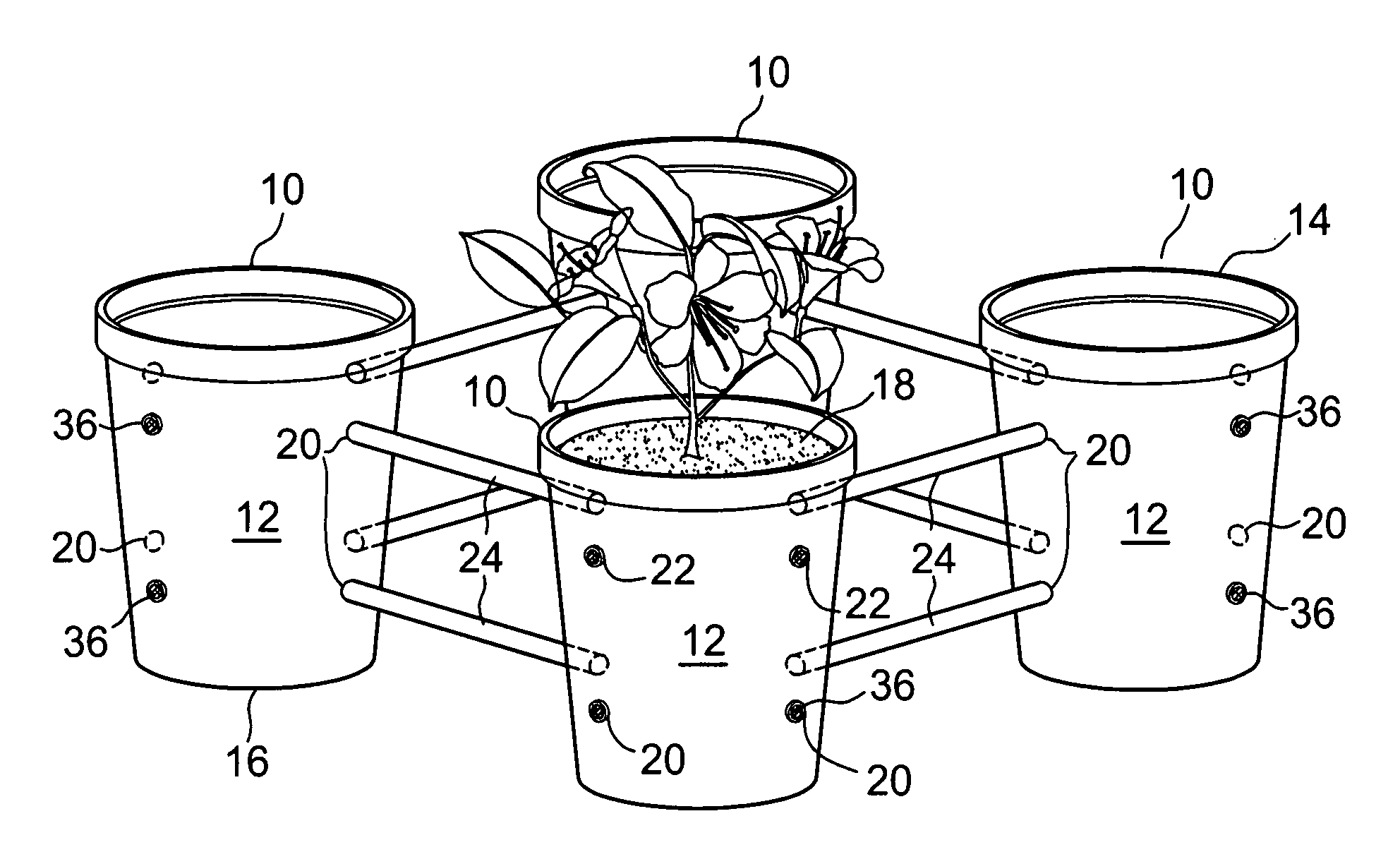
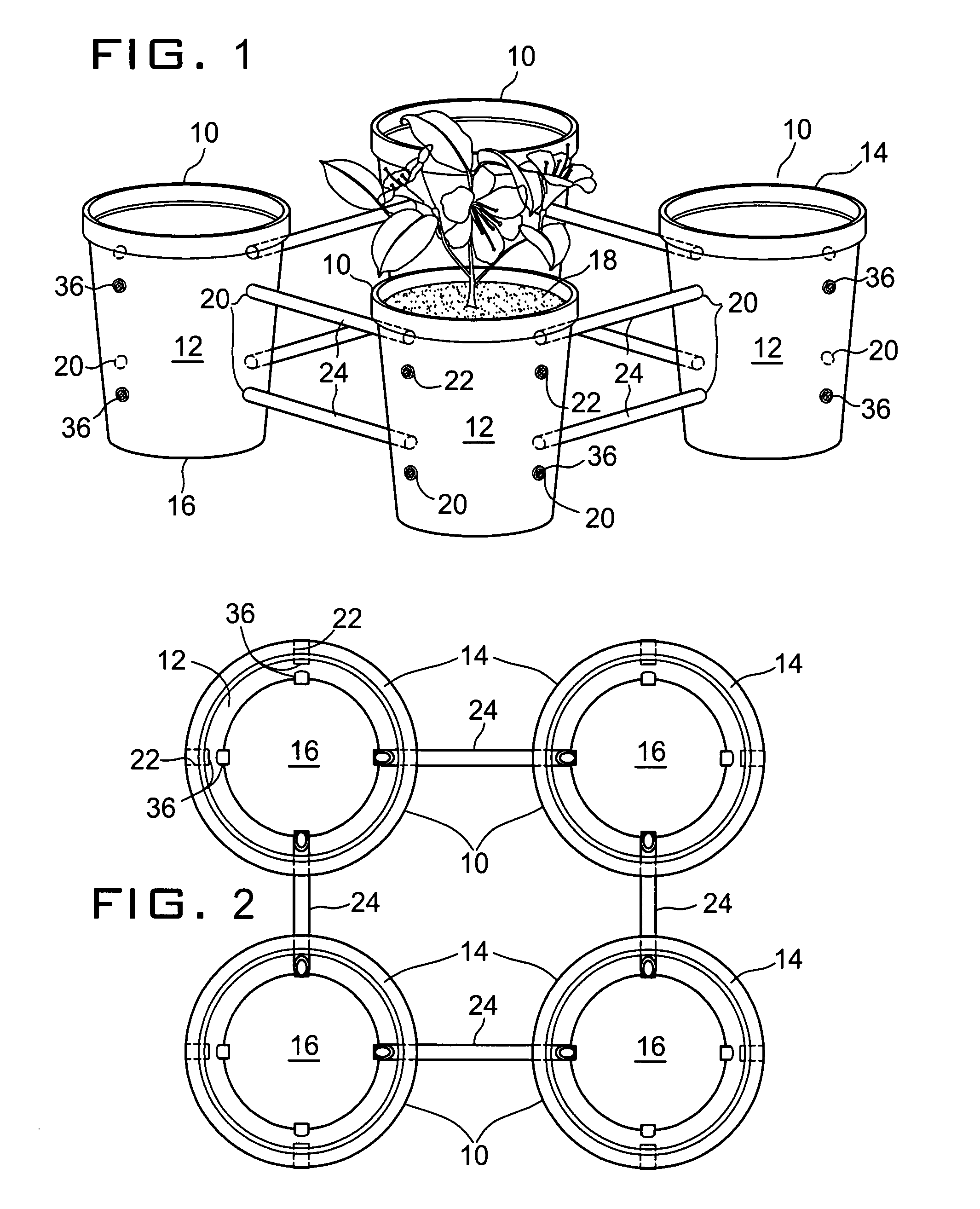
[0027]With reference to FIG. 1, a group of plant pots 10 according to the present invention is shown constructed in conventional manner except a matrix of watering holes on the sidewalls 12 of the pot 10.

[0028]The plant pot may also comprise a wider open top 14 and a narrower bottom wall 16 for containing planted soil 18 that receives a routine watering through the open top 14. The plant pot 10 may be in the form of a deep round vessel that is provided with eight round holes of which four holes 20 are positioned circumferentially at a lower level distanced one fourth of the height of the pot 10 from its bottom. The holes 20 may be formed at the same time of molding the pot 10 or bored through the pot walls horizontally and in parallel with the bottom walls 16. Then, the angular distance between the holes 20 becomes 45 degrees facing four different directions. Directly above the lower holes 20 are formed the same number of upper round holes 22 at about three fourth of the height of t...


PUM


Abstract

A plant pot system has at least one plant pot with side walls, an open top and a bottom wall for containing planted soil that receives a routine watering through the open top, the plant pot having two parallel rows of a number of through holes aligned circumferentially, each of the through holes being blocked by a removable closure; one or more additional pot members with the same number of through holes at levels corresponding to the through holes of the first plant pot; and at least one water leveling members for fluidly connecting any desired number of laterally disposed plant.

Description

BACKGROUND OF THE INVENTION[0001]A. Field of the Invention[0002]The present invention relates to a plant pot. More particularly, the present invention relates to a modular plant pot that can be grouped with multitudes of similar modular plant pots in fluid communications among them to automatically exchange a single water supply to any one pot with the rest of the pots in the same group minimizing wastes of daily planting water that constitutes a significant portion of water consumption in the nation.[0003]B. Description of the Prior Art[0004]A wide variety of self watering plant pots have been patented. U.S. Pat. No. 5,272,835 to Stern describes an example of self-watering pot comprising a doubled-walled container having an irrigation chamber embedded. The irrigation chamber contains a plurality of serially arranged irrigation ducts that reside just above the soil surface. A transport channel connects the irrigation chamber to a water input pipe extending through from the container...

Claims


Application Information

Patent Timeline
Patent Type & Authority Applications(United States)
IPC IPC(8): A01G27/04
CPCA01G9/027A01G27/00
Inventor JUNG, MAN-YOUNG
Owner JUNG MAN YOUNG
Why Eureka
Try Eureka