
Locking mechanism for a gate

a technology of locking mechanism and gate, which is applied in the direction of carpet fasteners, building components, dwelling equipment, etc., can solve the problems of difficult operation for children and pets on the one hand, and relatively simple for adults on the other

Inactive Publication Date: 2006-06-27
NUBIS
View PDF26 Cites 17 Cited by
  • Summary
  • Abstract
  • Description
  • Claims
  • Application Information

AI Technical Summary

Benefits of technology

[0006]The invention provides for this purpose a locking mechanism. The locking mechanism can thus be operated with only one hand; the operating element must be gripped and loaded in a direction differing from an operating direction such that it thereby engages on the latching member, and the latching member can then be simultaneously displaced by displacing the operating element. This operation requires a hand coordination such that operation is impossible for children and pets on the one hand but relatively simple for adults on the other. Depending on the desired specifications of use the operating element can be manufactured such that a determined minimal gripping force must be produced to cause engagement of the operating element. Another significant advantage of the locking mechanism according to the invention is that it can be manufactured very simply and at relatively low cost and is little susceptible to malfunction.
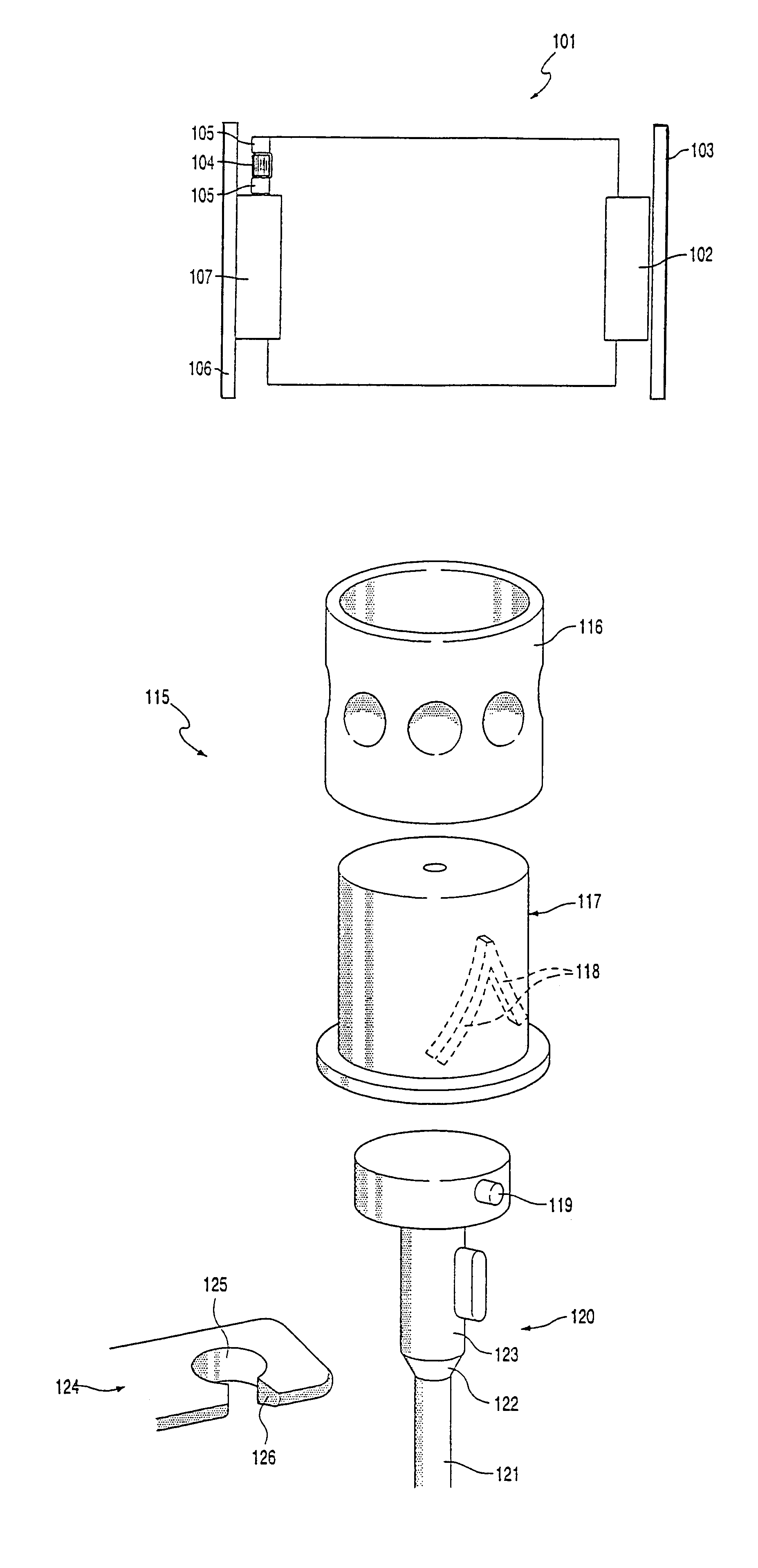
[0010]In another preferred embodiment the latching member is provided with a profiled surface part for co-action with a contact surface of the operating element directed toward the latching member. The contact surface of the operating element directed toward the latching member is preferably provided herein with a counter-profile. Owing to these measures a good engagement of the operating element on the latching member can be realized, this being desirable for optimal functioning of the locking mechanism. A good coupling between latching member and (deformed) operating element can thus also be realized in difficult conditions, such as for instance in the case of a jamming latching member or in damp conditions of use. As profile can for instance be envisaged an anti-slip layer, but also for instance a toothing with a counter-toothing as counter-profile.
[0012]Yet another embodiment variant is characterized in that the latching member is provided with a substantially helical guide. The kinematic reversal, a helical guide on which the latching member engages, likewise forms part of the present invention. When such a latching member is rotated using the operating member, this will result in an axial displacement of the latching member. A simple axial displacement is thus enabled for locking purposes by a rotating movement of the operating member which is simple in respect of operation. When it is not desired that the locking pin also make a rotating movement, the latching member can engage rotatably on a locking pin which is only linearly displaceable. It is hereby possible to prevent a rotating movement of the latching member being transmitted to the locking pin; only the axial displacement of the latching member need be transmitted.
[0018]In one embodiment at least one plate-like part can herein be transparent. It is hereby possible to look through the gate and to see what is situated behind the gate. This can be safe and comfortable for both the child and the adult.
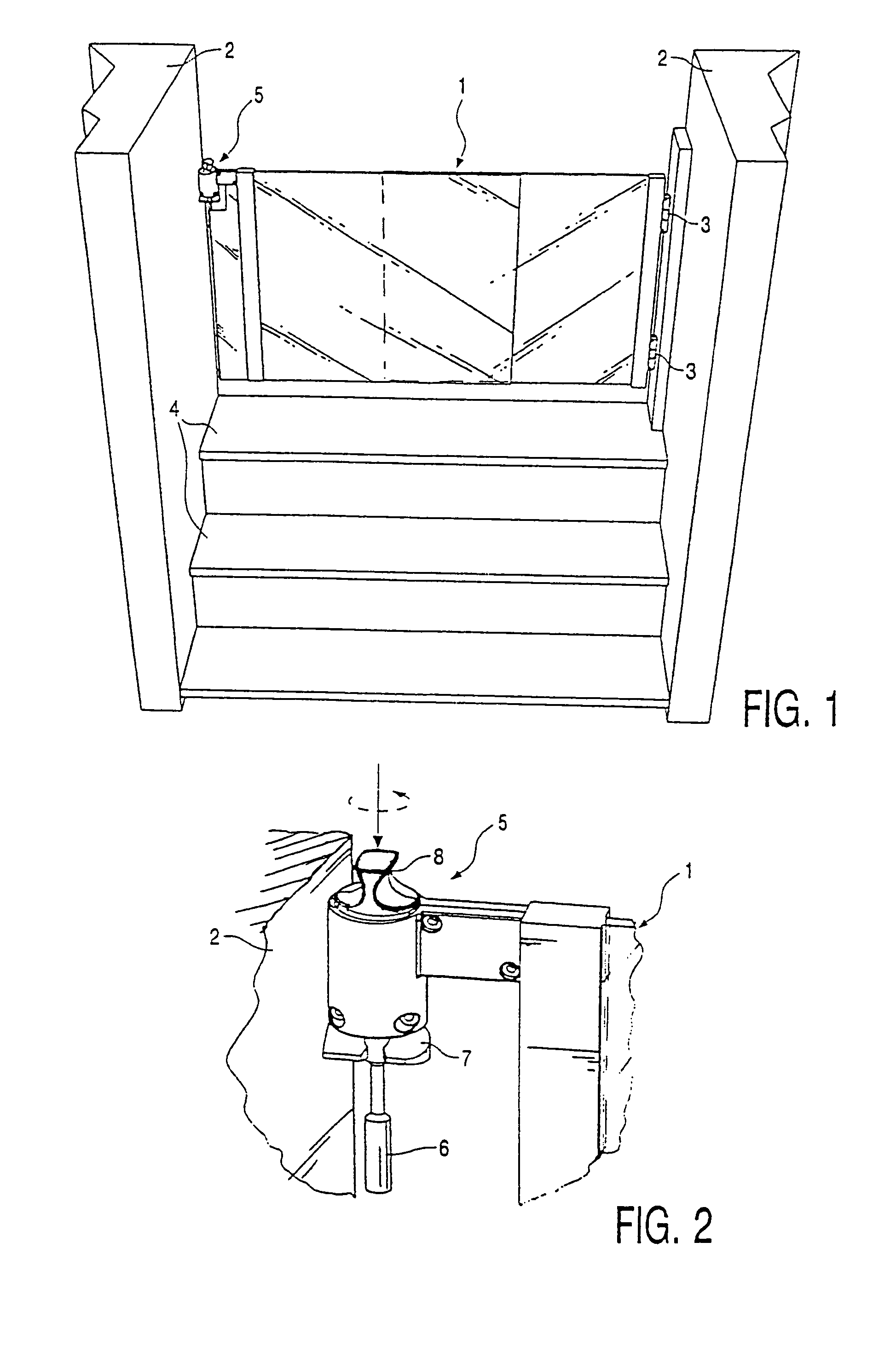
[0019]For certain safeguarding against undesired opening, the stair gate is preferably embodied such that the latching member is at least substantially screened off from the environment. It is hereby difficult or even impossible to grip the latching member directly and then move it. When the latching member is completely screened off from the environment, for instance in that the latching member is screened off from the environment by the guide, the operating element and the stair gate, the latching member can only be displaced by the operating element, which provides the desired safety.

Problems solved by technology

This operation requires a hand coordination such that operation is impossible for children and pets on the one hand but relatively simple for adults on the other.

Method used


Image

  • Locking mechanism for a gate
  • Locking mechanism for a gate
  • Locking mechanism for a gate

Examples


first embodiment

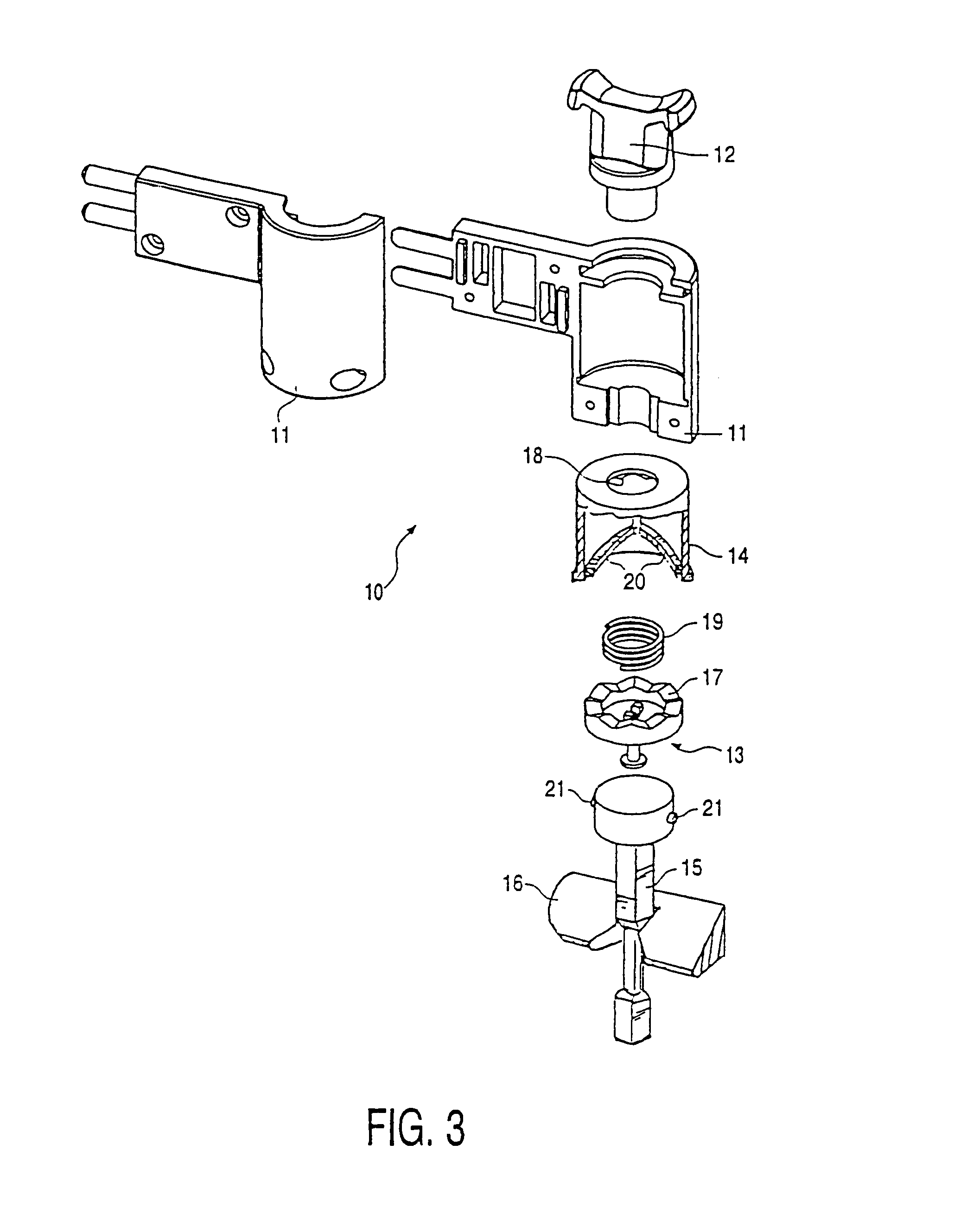
[0035]FIG. 3 shows a locking mechanism 10 with an axially displaceable operating member 12. Locking mechanism 10 comprises two housing parts 11. These housing parts 11 are adapted to receive an operating member 12, a ring 13 which is coupled thereto and provided with a toothing 17, a latching member 14 and a locking pin 15. This locking pin 15, which in this embodiment has a square cross-section, co-acts with a latching member 16 which can be fixed to a vertical wall part. On an inner surface the latching member 14 likewise comprises a toothing 18 which can co-act for rotatable coupling with the toothing 17 on ring 13. A spring 19 is further arranged in the housing for the purpose of urging apart the latching member 14 and ring 13.

[0036]Latching member 14 is provided with two helical ribs 20 on the surface of the inner periphery. These ribs 20 co-act with two cams 21 arranged on locking pin 15 so that locking pin 15 is lifted upward out of latching member 16 by rotation of the latch...

second embodiment

[0037]FIG. 4 shows a locking mechanism 30 according to the invention. This locking mechanism 30 also comprises two housing parts 31, in which an operating member 32, a latching member 34 and a locking pin 35 are received. Locking pin 35 is provided in this embodiment with two narrowed portions 36, which each fall into a latching member 37. Latching, member 34 has on its inner surface two helical ribs 38 which co-act with cams 39 arranged on locking pin 35.

[0038]The upper side of latching member 34 is provided with a toothing 40, which co-acts with a toothing 41 arranged on operating member 32. A spring 42 is arranged between operating member 32 and latching member 34 for the purpose of urging apart operating member 32 and latching member 34. In order to limit urging apart of the two parts 32, 34, a bounding part 34 is arranged on operating member 32.

[0039]In FIGS. 5A and 5B the locking mechanism 10 is shown in assembled state. The operation hereof is as follows. Operating member 12 ...


PUM


Abstract

A locking mechanism for a stair gate, comprising a displaceable latching member and an operating element which can engage on the latching member, wherein in a non-loaded state the operating element substantially releases the latching member and in a loaded state the operating element engages on the latching member, wherein for engagement on the latching member, the operating element is loaded in a direction varying from an operating direction of the latching member.

Description

BACKGROUND OF THE INVENTION[0001]1) Field of the Invention[0002]The invention relates to a locking mechanism for a stair gate, comprising a displaceable latching member and an operating element which can engage on the latching member. The invention also relates to a stair gate provided with such a locking mechanism. The invention furthermore provides a gate for closing off an opening between two vertical, fixedly disposed pans, wherein the gate comprises at least one hinge for hingedly mounting the gate on one of the vertical parts; and a locking mechanism for releasably coupling the part of the gate remote from the hinge to the other vertical part.[0003]2) Brief Description of the Prior Art[0004]Gates, particularly stair gates, are known in diverse embodiments and have as their most important function the screening off or blocking of a staircase in order to prevent undesired stair use. Stair gates generally consist of two frame parts with bars. These frame parts can slide along eac...

Claims


Application Information

Patent Timeline
IPC IPC(8): E05B65/06E05B65/00E06B9/04
CPCE05B65/0014E06B9/04Y10S292/27E06B2009/002Y10T292/1094
Inventor DE KRUIJF, WILHELMUS PETRUS JOHANNESMEEMS, BERRYVERTEGAAL, HENDRIKUS JOHANNES
Owner NUBIS
Learn More