Process and apparatus for uprooting trees

Inactive Publication Date: 2006-06-27
TREFAN LAJOS +2
View PDF8 Cites 5 Cited by
  • Summary
  • Abstract
  • Description
  • Claims
  • Application Information

AI Technical Summary

Benefits of technology

[0007]During the development of the invention our target was to invent a proper equipment and proces

Problems solved by technology

This accident-prone work is considerably slow.
Disadvantage of the method is that due to the high pulling power very often the timber breaks.
In this case very often the problem is that during the holding process of the root-trunk the tool gets clogged and consequently it is not able

Method used


Image

  • Process and apparatus for uprooting trees
  • Process and apparatus for uprooting trees

Examples


example 1

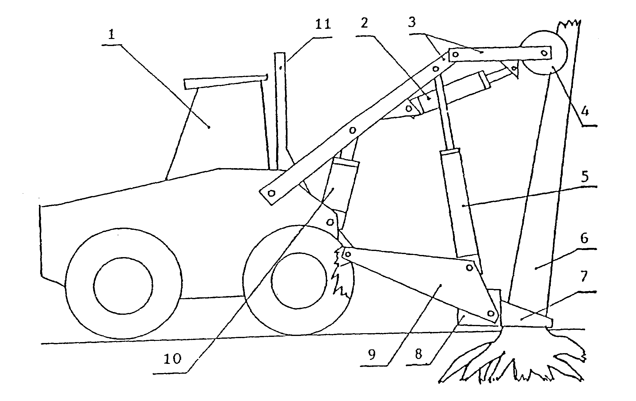
[0035]The equipment made according to this beneficial implementation is presented in FIG. 1.

[0036]In this case the timber holding frame (9), the supporting frame (3) and one or more elevating working cylinders (10) are connected to the power machine (1) all in a rotatable manner. The other end of the elevating working cylinder (10) is connected to the supporting frame (3) and consequently providing the height setting of the latter one. There is / are one or more throwing working cylinder(s) (5) between the supporting frame (3) and timber holding frame (9). This way the position of the latter ones is adjustable. The upper connecting point of the throwing working cylinder (5) may equally be the part of the supporting frame (3) being nearer to the power machine (figure shows this solution), or the part being nearer to the supporting cylinder (4). The two parts of the supporting frame, i.e. the one which holds the supporting cylinder (4) and the other which is coupled to the power machine...

example 2

[0041]Deviations from the set-up presented in the Example 1 and FIG. 1 are as follows. This implementation is shown in FIG. 2.

[0042]The supporting frame (3) is not an articulated device except its hanging-up. The upper part of the throwing working cylinder (5) is connected in a flexible manner to the adjusting tool (2). The lower (other) part of the adjusting tool (2) is connected to the supporting frame (3). Since one end of the elevating working cylinder (10) is connected to the power machine (1), the elevating working cylinder (10) does not control the movement of the supporting frame (3) but either directly or via an armed-articulated device (as it is presented in the Fig.) it is able to arrange the movement of the timber holding frame (9) relative to the earth and the power machine.

[0043]The cutting-down of the tree and the operation of the equipment are the same as it is described in Example 1.


PUM


Abstract

The subject of the invention is the excavation of trees by disrooting then by a hydraulic equipment, when the power machine (1) is connected in a rotatable manner to the timber holding frame (9), the supporting frame (3) and the elevating working cylinder (10); the timber holding frame (9) is connected to the timber holding equipment (8), wich is able to catch the timber (6) by its arms (7); the timber holding frame (9) is connected to the throwing working cylinder (5) and the supporting frame (3) is attached in a rotatable manner to the supporting cylinder (4); and in case of articulated setting-up of the supporting frame (3) the movement of the two parts of the supporting frame is done by the adjusting tool (2); then the upper part of the throwing working cylinder (5) is connect to any part of the supporting frame (3); furthermore the other end of the elevating working cylinder (10) is connected to the supporting frame (3) or in case of rigid joint setting-up of the supporting frame (3) one end of the adjusting tool (2) is connected to it, while the other end to the throwing working cylinder (5); furthermore the elevating working cylinder (10) can be connected to the timber holding frame (9) directly or via articulated power transmission.

Description

BACKGROUND OF THE INVENTION[0001]The subject of the invention is an equipment for the excavation of trees by disrooting them and a process for taking down the trees by this way.[0002]Basically there are two types of processes for lumbering, i.e. separation of the bole from the root-trunk, and the assart. In the first case the root-trunk being remained in the earth after chopping down the bole is regularly extracted separately by forked pushing tools or tines mounted on a tractor (using considerable large stroke) or e.g. by blasting. According to the current methods grubs can be used as well. One type of them drills into the root-trunk and slices or splinters it. The other type drills around the root-trunk with a sharp cylinder, cuts the roots and finally excavates the root-trunk.[0003]In case of assart the separation of the bole from the earth is done below the terrain level. If the root-trunk should also be excavated being as a more favourable solution regularly this method is used...

Claims


Application Information

Patent Timeline
IPC IPC(8): B66F3/00A01G23/06A01G23/08
CPCA01G23/065
Inventor TREFAN, LAJOSTREFAN, SZABOLCSTREFAN, SZILARD
Owner TREFAN LAJOS
Why Eureka
Try Eureka