Damping type electric lifting type fan
A lift-type fan technology, applied in the field of electric fans, can solve problems such as high noise and excessive motor vibration, and achieve the effects of low operating temperature, reduced vibration, and flexible methods
- Summary
- Abstract
- Description
- Claims
- Application Information
AI Technical Summary
Problems solved by technology
Method used
Image

Examples
Embodiment example 1
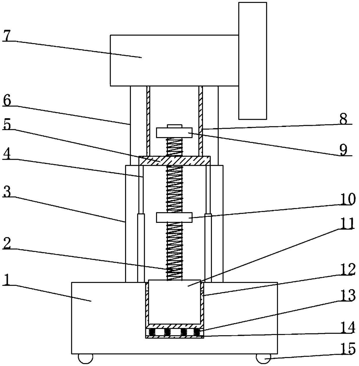
[0025] Implementation Case 1: A shock-absorbing electric lifting fan, including a base 1 and a fan 7, the fan 7 is arranged on the base 1, a lifting assembly is arranged between the base 1 and the fan 7, and the lifting assembly Including servo motor 11, screw rod 2, lifting plate 5, lifting rod 8 and telescopic rod 4, the base 1 is provided with a mounting groove, the servo motor 11 is arranged in the mounting groove, and the upper end of the servo motor 11 is connected by transmission The screw rod 2, the upper end of the screw rod 2 is threadedly connected to the lifting plate 5, the lifting rod 8 is fixedly connected to the lifting plate 5, the upper end of the lifting rod 8 is fixedly connected to the fan 7, and the lifting plate 5 The telescopic rod 4 is arranged between the base 1, and the noise reduction assembly is arranged between the driving motor 11 and the mounting seat. The noise reduction assembly includes a damping plate 12, a shock absorbing spring 13 and a rub...
Embodiment example 2
[0027] Implementation Case 2: This implementation is further optimized on the basis of Embodiment 1. This embodiment focuses on the improvements compared with Embodiment 1, and the similarities will not be repeated. Further optimization of the present invention, the screw 2 The upper end of the screw rod 2 is provided with an upper limit block 9, and the lower end of the screw rod 2 is provided with a lower limit block 10. By being provided with an upper limit block 9 at the upper end of the screw rod 2, the upper limit block 9 prevents the lifting plate 5 from colliding with the described The installation plate collides and damages the access control components, reducing potential safety hazards and improving safety; the lower end of the screw rod 2 is provided with a lower limit block 10, and the lower limit block 10 prevents the lifting plate 5 from colliding with the servo motor 11 during the descent process. Servo motor 11 reduces potential safety hazards and improves prac...
Embodiment example 3
[0028] Implementation Case 3: This implementation is further optimized on the basis of Embodiment 1. This embodiment focuses on the improvements compared with Embodiment 1, and the similarities will not be repeated. The further optimization of the invention, the lift assembly The outer side is covered with a telescopic sleeve, the telescopic sleeve includes an upper sleeve 6 and a lower sleeve 3, the upper side of the upper sleeve 6 is fixedly connected to the fan 7, and the upper sleeve 6 is sleeved with the lower sleeve 3. The upper sleeve 6 is slidably connected to the lower sleeve 3, and the lower side of the lower sleeve 3 is fixedly connected to the base 1. A telescopic sleeve is provided on the outer side of the lifting assembly, and the upper and lower sleeves can slide up and down. The upper sleeve 6 and the lower sleeve 3 improve the stability between the fan 7 and the base 1, and can be protected by the servo components to improve the service life of the servo compon...
PUM
 Abstract
Description
Claims
Application Information
 - Generate Ideas
- Intellectual Property
- Life Sciences
- Materials
- Tech Scout
- Unparalleled Data Quality
- Higher Quality Content
- 60% Fewer Hallucinations
Browse by: Latest US Patents, China's latest patents, Technical Efficacy Thesaurus, Application Domain, Technology Topic, Popular Technical Reports.
© 2025 PatSnap. All rights reserved.Legal|Privacy policy|Modern Slavery Act Transparency Statement|Sitemap|About US| Contact US: help@patsnap.com